
Digital Debunking: Can Simulation Make Hypersonic Travel Commercially Viable?
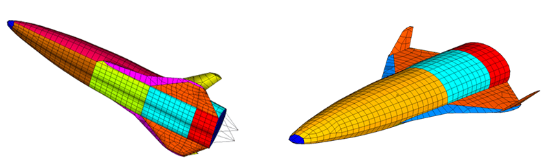
Hypersonic travel is associated with speeds more than five times the speed of sound within Earth’s atmosphere. Today, engineers have achieved air travel reaching over 7 times the speed of sound. The potential for hypersonic flights – a flight that occurs above Mach 5, which is more than 3,000 mph – could make air travel faster and more efficient than ever. Vehicles designed to fly at hypersonic speeds (or re-enter the atmosphere in some cases) must be designed to withstand aerodynamic and inertia, heat, and acoustic loads that these high speeds create. You can see the difference between the designs of commercial aircraft and hypersonic vehicles here – note the sleeker, more compact, and more rigid frame. But while hypersonic travel is typically seen in government and military applications, many people want to see hypersonic travel become commercially viable for everyday travelers.
Due to the extreme demands hypersonic travel imposes on a vehicle’s structure, selecting hardy, flexible materials and minimizing structure weight is vital to keep vehicles capable and safe. For example, if you watch a rocket re-enter Earth’s atmosphere, you might see a giant fireball forming across the front of the vehicle – this phenomenon occurs because of the heat generated at these extreme speeds and the high amount of energy lost because of friction.
Air vehicles face two main challenges when traveling in these conditions. The first challenge is designing a propulsion system capable of reaching hypersonic speed. The second is designing the vehicle’s outer shell so it can withstand the tough environment around it when traveling at hypersonic speed.
A hypersonic vehicle’s outer structure also faces turbulent boundary layer excitation that causes significant vibration because of the high Mach speeds. The outer structure is part of the vehicle’s thermal protection system; yet at the same time, it must have rigid structural integrity to support aerodynamic and inertia loads. Therefore, it’s crucial that engineers and designers select heat-resistant, sturdy materials to ensure these vehicles’ success. Without the right materials and solid design, the internal compartment of the vehicle that contains the payload, the electronics, and passengers would be subjected to searing, inhospitable heat.
To understand hypersonic vehicle design requirements, our team applied APA partner MES’ technology to a generic hypersonic vehicle model. MES’ work determines the type of material and sizing of aeroshell outer structures and thermal blankets to minimize weight, keep structural stresses and vibration levels below prescribed limits, and provide sufficient thermal protection for the inner structure. This type of concurrent design study is necessary when configuring aircraft structures that will be suitable for hypersonic travel and need to take to the skies at the lowest possible weight. What our team wanted to find out is, Could hypersonic vehicle technology be suitable for widespread commercial airline adoption one day?
Modeling the Ceramic Matrix Composite (CMC)
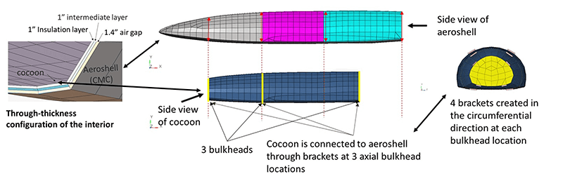
To begin modeling a realistic hypersonic vehicle, our team used Michigan Engineering Services’ (MES) energy finite element analysis (EFEA)’s multi-layer approach for modeling the aeroshell, which we created using a standard CMC configuration encountered in hypersonic technology.
Next, we used a representative finite element model of a hypersonic vehicle to demonstrate how the EFEA can compute the vibration of the aeroshell and at the locations where electronics and payload would be mounted. The modeling steps we used are as follows:
- Create an interior payload structure with stiffeners and bulkheads and attach it to the exterior aeroshell
- Utilize semi-empirical turbulent boundary layer (TBL) models for hypersonic flows from the literature for defining the excitation on the aeroshell
- Conduct the EFEA analysis to determine aeroshell vibration
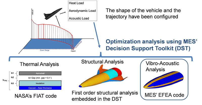
We then used the MES Decision Support Toolkit (DST) product to determine which materials to use, how thick to make the aeroshell, and the thermal blankets for minimum mass. The EFEA code and simulation tools for structural and thermal analysis are linked to the DST for determining the vibration, structural, and thermal performances for every combination of material selection and thicknesses that can be considered.
Conducting the Design Study
To begin the analysis, we selected materials and sizing for the aeroshell and thermal blankets. We then applied thermal, stress, vibrations induced by acoustic loads, and minimum thickness constraints so we could observe them during the analysis.
Design variables are the parameters that are adjusted to meet performance expectations for thermal protection, maximum stresses, and maximum vibration levels to reach an optimized weight. In this example, the material selection for different types of CMC and thermal blankets along with their thicknesses comprised the design variables. We divided the vehicle into eight sections: four upper and four lower.
Due to practical construction considerations, all eight sections for the aeroshell had to have the same thickness. Also, we had to make a single material selection for the aeroshell. We then made thermal blankets that are made of non-structural, thermal isolation materials and placed them outside the vehicle’s inner structure in the space between the inner structure and the aeroshell. This arrangement allows flexibility to select a different material and thickness for the thermal blanket placed in each one of the eight sections. A total of 19 design variables could be adjusted to minimize the total weight subject to the performance expectations.
Studying the Acoustic Loads
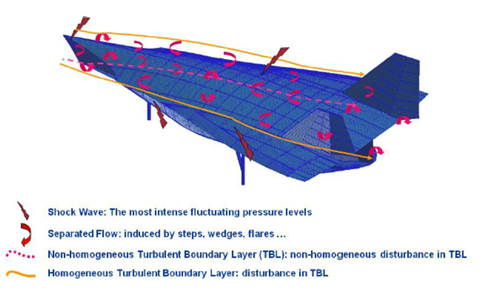
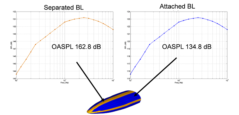
In the figure below are typical locations of a hypersonic aircraft from the publicly available report AFRL-RB-WP-TR-2010-3068, V1 with high acoustic loads due to separated flow and shock. The sections toward the vehicle’s midsection and sides (identified with the red arrows) are the ones where we encountered separated flow and/or shock waves. These locations faced a much higher acoustic load compared to the rest of the locations, which experienced the attached boundary layer flow. The acoustic loads were the driving excitation for the EFEA computations.
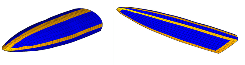
The images above present the EFEA model. The areas in blue are loaded with a lower acoustic load associated with an attached boundary layer flow. In orange, the areas are loaded with a higher acoustic load from separated boundary layer flow and shock.
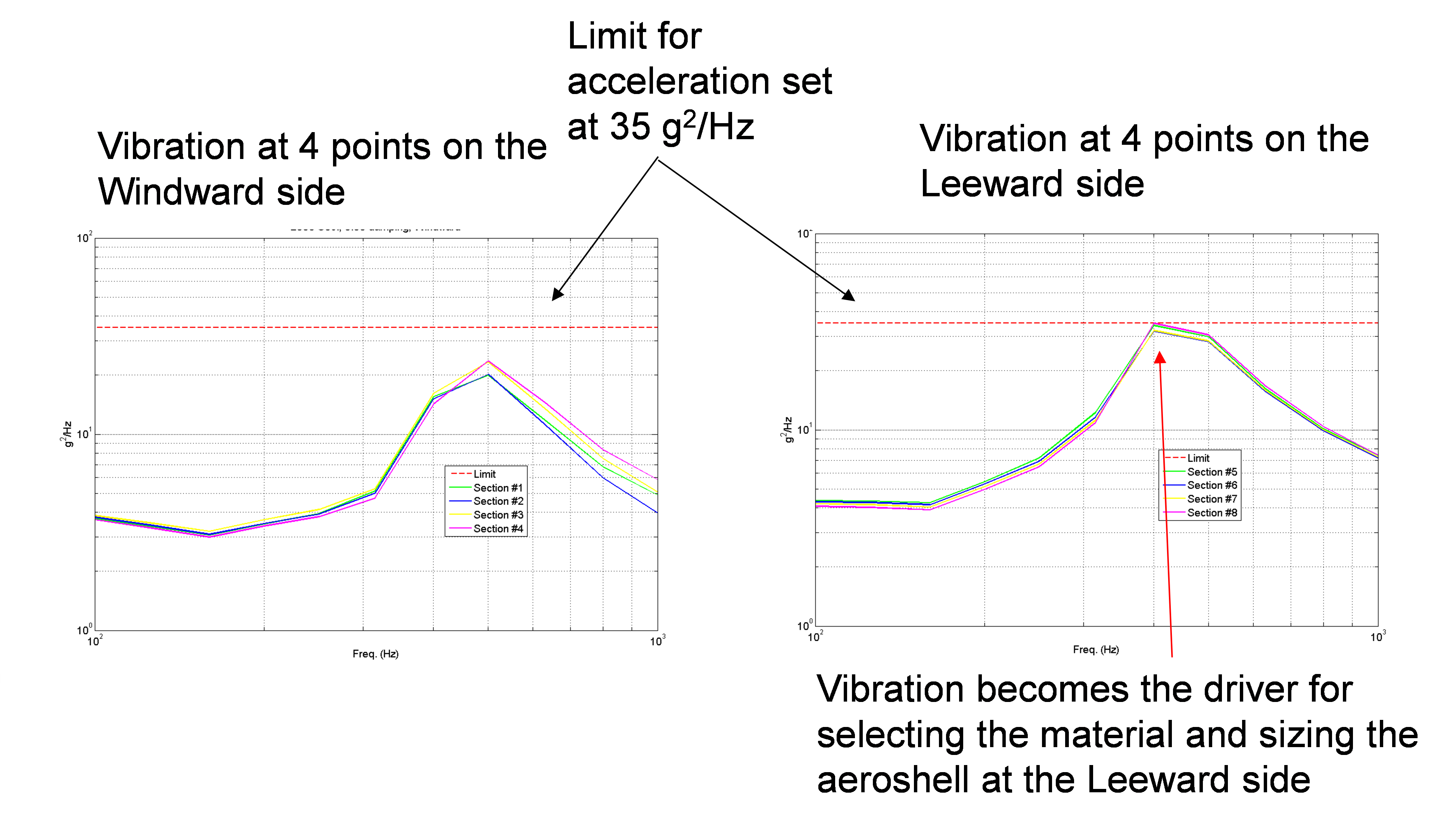
We applied typical acoustic loads on the EFEA model of the hypersonic vehicle, shown in the figure below. We considered a maximum acceleration of 35 g2/Hz as the vehicle’s acceptable upper limit. We determined the overall sound pressure level (OSPL) of the loading based on parameters such as the Mach number, altitude, and dynamic pressure. As we can see, the excitation had significant components in the frequency range of 800Hz – 10,000Hz. In such high frequencies, conventional finite element methods would require hundreds of thousands of elements to perform an analysis, which would require hours of run time.
Given that during a design analysis, several thousands of different configurations are considered and analyzed, it would be nearly impossible to perform the design optimization computations using conventional finite elements. The EFEA model runs much faster and performs the analysis for the entire frequency range within just a few minutes. The computational efficiency of EFEA enables conducting the vibration analysis within the highly iterative design process quicker and easier.
Determining Thermal/Stress Constraints and Selecting Material
An advanced carbon-carbon (ACC) and a reinforced carbon-carbon (RCC) type of CMC were considered for the exterior part of the vehicle; the RCC has a lower density compared to the ACC. Each material has a different set of maximum temperature limits, and maximum stress limits in compression, tension, and hoop stresses. Thermal insulation materials of an advanced blanket, an alumina enhanced thermal barrier (AETB), and a felt reusable surface insulation (FRSI) were considered as alternatives for the thermal insulation placed in between the outer shell and the inner structure. Each alternative material exhibited different density and maximum temperature limits.
During the optimization study, we evaluated each configuration for its structural and thermal performance. We conducted a structural analysis by considering the aerodynamic and inertia loads exerted on the outer structure. We determined the structural integrity based on how high the stresses were and if buckling occurred. The thinner the sizing of the structure, the more difficult it became to meet the strength requirements. Therefore, the team ran into a trade-off between the outer shell’s weight and its structural performance.
Next, we conducted a thermal analysis. The outer shell along with the insulation material and the air gap in between comprised the thermal protection system (TPS). The thermal analysis evaluates the temperature histories experienced within each layer of the TPS and the temperature at the outer part of the internal structure. All such temperature time histories were monitored and compared to the maximum allowed temperature limits. Material selection and the sizing of the layers was pursued to minimize overall weight without exceeding the maximum temperature allowed in each layer.
Maximum Vibration Results for Optimal Configuration
Then, we monitored the vibrations occurring at eight sections of the outer shell of the vehicle. In general, when searching for the optimal configuration, vibration becomes a design driver; in other words, once the maximum vibration is reached, the thickness of the material and therefore the associated mass cannot be reduced anymore without exceeding the vibration limit. In this example, we encountered the maximum vibration level was encountered on the top (leeward) side of the vehicle. The figure below presents the results for the vibration of the optimal configuration.
Optimization Results
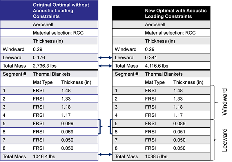
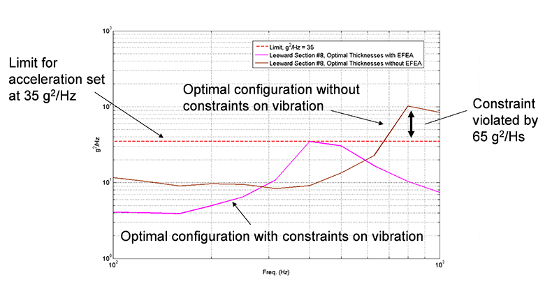
The table below, on the right side, summarizes the optimization results in terms of the material selection, associated thickness of each layer, and the resulting mass. The table on the left contains a summary of optimization results, but without considering any constraints on the vibration levels experienced by the vehicle. In the latter configuration, a higher reduction in the mass can be achieved due to a much lower thickness permitted on the top side of the outer shell. Nevertheless, when the EFEA analysis is not used during the optimization study for computing the vibration levels and limiting it by the maximum value of 35g2/Hz, the resulting configuration experiences a much higher vibration compared to the limit.
The second figure below presents this situation by comparing the maximum acceleration encountered in the optimal configuration when the vibration constraints were considered, versus the optimal configuration when only thermal and structural constraints were considered, but not the vibration constraint. Therefore, it is important to account for the vibrational performance of this vehicle during the design, along with structural and thermal performance expectations, otherwise poor performance can be discovered too late after an optimal design has already been chosen. At that point, a redesign effort is costly and will introduce delays in the overall development schedule.
Conclusion
So, will we see commercial airlines adopting this technology in our lifetime? It’s hard to say, but it’s not out of reach. This technology was once thought to be impossible, yet we’re seeing technological breakthroughs every day. Although hypersonic flights’ fuel and ticket costs would undoubtedly be higher than the cost of regular commercial air travel, it’ll be interesting to see if and how companies implement these types of flights alongside their traditional offerings. With technology like EFEA by MES, engineers and scientists can simulate and optimize complex aerospace designs fast and accurately. Whether applied on a commercial or government level, solution-specific workflows streamline decision-making and find optimal aeroshell designs within a single platform.
What we do know for sure is that the EFEA solver offered key results for this aircraft’s design and optimization. The outer shell of a hypersonic vehicle needs to exhibit sufficient strength to withstand aerodynamic and inertia loads. In addition, it needs to meet thermal requirements as it is a part of the TPS that protects the interior vehicle structure from severe loads. Because of the quick run times EFEA technology offers, studying vibration performance, acoustic loading, and thermal and structural performance during a highly iterative design process is easier than using traditional methods.
This is key when vibration requirements become a design driver, and in the case of a hypersonic vehicle, when safety and minimal vibration is vital. Implementing a simulation-driven design approach early in the design process helps designers avoid the inconvenience of discovering excessive amounts of vibration too late at critical vehicle locations, when changes are difficult to make due to budgeting, severe reworks, time delays, and cost overruns.

About EFEA by Michigan Engineering Services (MES)
With MES’ (www.miengsrv.com) Energy Finite Element Analysis (EFEA) solver, users can perform vibration analysis of complex systems faster than ever using finite elements. As shown here, the EFEA solver can address the vibrational behavior of an aeroshell alongside its aerodynamic, aerothermal, thermal, and stress computations when selecting material and size early in the design process, rather than discovering vibrational behavior errors late in the design process, when they are more difficult and costly to correct.
The solver technology has been validated in multiple industries with successful applications in Naval vehicles, automobiles, and aircraft. Its technology enables users to perform mid- to high-frequency analysis without requiring multiple design elements and can be accessed through the Altair Partner Alliance (APA).
To learn more, visit https://www.altair.com/efea/.