
Accelerate Thermo Fluid Systems Design using Flow Simulator
Power generation ability came into existence during the First Industrial Revolution era when the first Steam Turbine was designed. By the Second Industrial Revolution, engineers were able to produce reliable electricity for modern life. Ever since, designing best-in-class power generating equipment remains a challenge for engineers to-date. Initially, engineers had to simplify complex fluid transport problems to 1D approximations to understand the behavior of the component design. By the time computers came into existence during the Third Industrial Revolution, 3D Computational Fluid Dynamics (CFD) simulations became very helpful in the product development stages. Even today, with the most powerful computers in existence, CFD Simulations are done on a component level as building large models is still time-prohibitive in the development process.
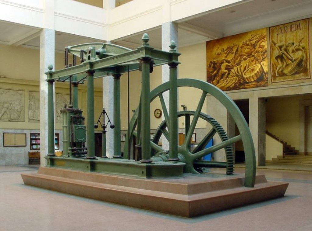 Photo Credit Wikipedia: A late version of a Watt double-acting steam engine, built by D. Napier & Son (London) in 1859, now in the lobby of the Superior Technical School of Industrial Engineers of the UPM (Madrid). Steam engines of this kind propelled the Industrial Revolution in Great Britain and the world.
In the age of digitalization, or as the industry calls it - the “Fourth Industrial Revolution,” systems engineering is gaining significant momentum. In the engineering world, Modal Based Systems Engineering (MBSE) is the formalized application of modeling to support system requirements, design, analysis, verification and validation activities beginning from the conceptual design phase and also, continuing throughout development life-cycle phases.
To meet the demand of shorter product development cycles and stringent requirement on emissions, engineers must rely on the best of 1D, 2D, and 3D CFD models to design aero thermal fluid systems.
Thermo Fluid Systems Design
Thermo fluid systems design deals with the principles of thermodynamics, fluid mechanic heat transfer and combustion application in the integrated system design. Thermo fluid systems modeling allows for the analysis of a wide range of complex engineering problems.
For example, in the turbomachinery industry, predicting the aerothermal characteristics of engine sealing systems, structures cooling, rotating cavity systems, component cooling, combustor design and optimization, lube oil systems, and thermal management of engine through the severe harsh working conditions of long transient flight missions are all challenging thermo fluid systems applications.
GE’s Flow Simulator:
In 2018, Altair announced a collaborative agreement with GE to commercialize Flow Simulator, a flagship product for mixed fidelity thermo fluid systems design and analysis. [February 2021, Altair announced the acquisition of Flow Simulator] Flow Simulator’s unique features include:
- An intuitive GUI that gives users the ability to overlay/integrate the 3D digital CAD with the analytical models
- Flow network (compressible sub/super-sonic, incompressible, steady & transient, rotating cavity windages)
- Thermal network (1D lumped mass, convection/conduction/radiation, HTC correlations library, custom materials)
- Combustion (equilibrium chemistry, species tracking, combustor diffusion, air/fuel mixing models)
- Control and optimization methods to explore the entire design space of the system
“Using Flow Simulator, designers can run a full probabilistic analysis to understand every possible way our customers can run their engines, and the impact of manufacturing variation on pressures and flow rates, all on their desktop workstation,” said Kevin Kirtley from GE Power.
After Burner Design Example
Flow and thermal network models are built from the existing library of elements available in Flow Simulator that are thoroughly validated. In this example, we studied the behavior of the afterburner flow physics and predicted the liner temperature. The objective was to understand pressure drop characteristics due to the mixing of the bypass flow with the core flow at various axial stations with different hole alignment. Thermal network elements can be coupled with flow network elements in the same model to study the effect of Rayleigh losses due to heat addition.
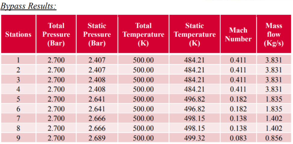
Initially, we modeled only flow network and solved the problem with and without friction to understand the mass flow splits in the core flow and bypass flow. The results can be seen visually on the GUI or can be exported to tabular format as shown below or can be plotted.
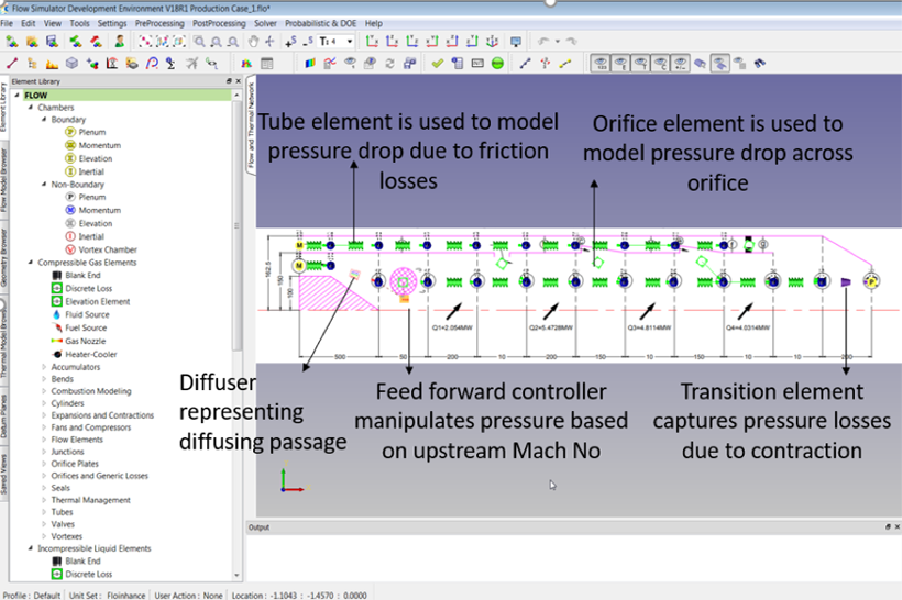 Figure 1: Flow Network Model of After Burner Example
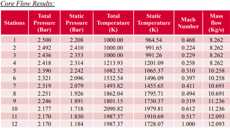
In the same model, the thermal effects can be added by using lumped mass elements to define the thermal network connecting with Flow networks as shown below.
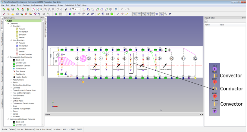 Figure 2: Intergraded Thermal Network and Flow Network Models of After Burner Example
Interested in learning more? Explore the features and capabilities of Flow Simulator