

Advanced Forming Research Centre Uses Altair EDEM™ to Determine the Powder Deposition Process in Laser Metal Deposition Additive Manufacturing
Guest post from James Black, Ryan Devine, Andrew Baker, and Jack Meiklejohn from the University of Strathclyde’s Advanced Forming Research Centre (AFRC)
Laser metal deposition (LMD) is an additive manufacturing process whereby a laser is used to create a molten pool of metal on a substrate material; into which metal powder is deposited. Complex 2D geometries can then be constructed on the substrate surface and the process can be repeated for a number of layers to manufacture complex 3D components in a manner similar to polymer 3D printing.
The process holds many advantages over traditional subtractive manufacturing techniques, such as CNC machining. Significantly less material is wasted when components can be directly printed, providing huge cost savings, particularly in the manufacture of components which require advanced, high-cost materials. Additionally, different powdered metals can be mixed prior to deposition, allowing for builds with compositional gradients which can improve material compatibility and performance.
The University of Strathclyde’s Advanced Forming Research Centre (AFRC), part of the National Manufacturing Institute Scotland, is one of seven centres that make up the High Value Manufacturing Catapult (HVMC), a group of manufacturing research centres set up to help advance the UK manufacturing industry. The machining and additive manufacturing team at the AFRC is continually striving to further-enhance the centre’s LMD capabilities. The Renfrewshire-based centre has its own hybrid machine, capable of both LMD additive and CNC subtractive manufacturing in the one platform.
To gain a better understanding of the overall process, the team at the AFRC worked with EDEM software to model the deposition of the powder from the LMD head while incorporating fluid-particle and laser-particle interactions, using CFD and Mie Theory respectively. This has been done with the hope that in the future, more developed models will be able to inform and optimize the LMD process improving the quality of AM components.
An essential phase of the project was to calibrate the EDEM simulations so that the powder used in the simulated results was comparable to the real powder under investigation. This involved carrying out physical experiments to determine the coefficients of sliding and rolling friction (μs and μr) for the particle-particle and particle-equipment material interactions. μs was measured experimentally while μr was determined following a traditional DEM calibration procedure. Ideally the coefficient of restitution would also be experimentally measured, however this would require highly sophisticated equipment which was beyond the project scope. Instead, a placeholder value of 0.5 was used, similar to what has been used in other studies [1].
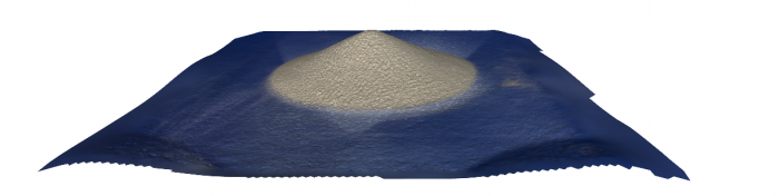
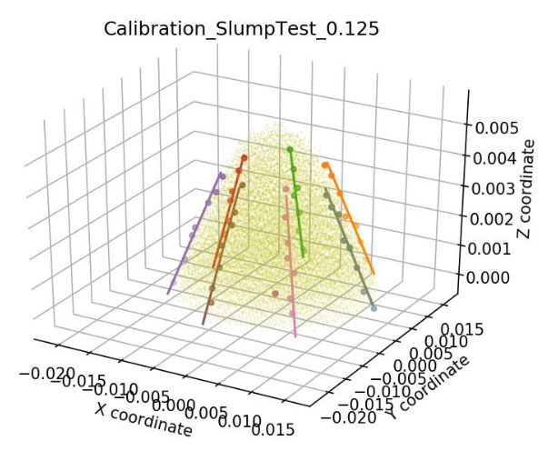
The static slump test was chosen as the calibration experiment used to investigate the particle-particle interactions. The static slump test involves pouring powder into a vertical hollow cylinder, allowing the powder to come to rest and then lifting the cylinder. The coefficient of sliding friction can then be calculated by measuring the angle the slumped powder pile makes with the horizontal, known as the Angle of Repose (AoR). AoR is related to μs by the following equation which can be derived from the free body diagram of an object sliding down a slope [2]:
μs = tan(AoR)
The angle of repose was measured manually using a digital protractor. These measurements were then further validated by using Standard Cyborg’s Capture App to create an IR point-cloud scan of the powder pile. The AoR of the scanned model was then measured using a Python script and the results were within 1 degree of the manual measurements.
This test was chosen for 2 main reasons: the physical experiment is simple and low-cost, and the numerical experiment already exists as part of EDEM’s Calibration Kit. The Calibration Kit is integrated with EDEMpy to measure the AoR directly from the EDEM workbench model, greatly improving the accuracy and convenience of the numerical experiment.
The particle-equipment material μs was measured experimentally using a sliding plate test. In this test, a very thin layer of powder was spread over a plate of equipment material (in this case brass). The brass plate was slowly angled until the layer of powder slid off of the plate. The angle the plate was at when this occurred was then taken as the AoR. This test was not featured in the EDEM Calibration Kit and so a custom EDEM experiment was set up. A static factory was used to quickly generate the layer of powder particles and the plate was rotated about one end at a set angular velocity. The test was run until the particles slipped off the plate and the AoR was calculated by simply multiplying the time at which this occurred by the angular velocity. μs was then calculated using the previously mentioned equation.
The μr is more difficult to determine experimentally. Instead, once both values of μs had been calculated the value of μr was incrementally changed until the AoRs from the EDEM simulations matched those from the physical experiments. This calibration procedure could be repeated for a range of different materials and powders, provided that new physical experiments were carried out.
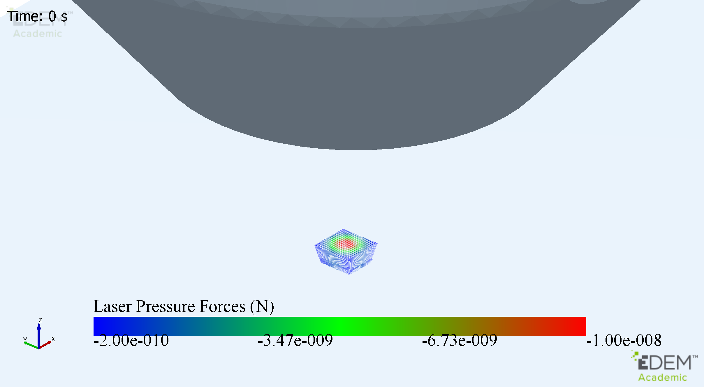
To make the EDEM model more representative of the gas-particle interaction within the nozzle, it was necessary to include Particle Body Forces that act upon the material. The two that were analyzed were the pressure forces from the laser and the aerodynamic forces from the various gas flows introduced by the nozzle. To implement these forces, a custom plugin was created using the Application Programming Interface (API) provided by EDEM.
This was comprised of different interfaces that provided the necessary methods and structure to add these forces during each calculation iteration. The code created was a single class that was derived from the “ParticlePluginForcesV3_1_0.h” interface that was provided as part of the API. Using this interface, and some other tools also provided in the API, the codes that could implement the forces from the laser were generated. This was done by adding the components of the force in each discrete region to a particle if it happened to be in the laser beam area. The particles were treated as a point mass located directly at their centre and thus this position was used to determine which laser forces to apply.
This simplified the problem, as in reality the particles were significantly larger (x5) than the discrete laser force regions. This meant that each particle would experience different forces over its surface when in the laser beam. This could have been solved by a surface integration scheme; however, this would have significantly increased the complexity and it was decided this was out with the scope of the project. A linear interpolation scheme between the particles and their nearest neighbouring forces was instead used, as one already existed in the API.
To consider the aerodynamic forces that act on the particles from the various gas flows, a one-way coupled CFD-DEM analysis was carried out. Since the CFD data was 2-dimensional, a method had to be developed to create 3D information from this. To get around this, the solution was to virtualise the 3D vector field into 2D. The algorithm implemented first checked if the particle was within 75mm of the centre of the flow field. Then it found a matrix transformation that rotated this particle into the 2D vector field plane; searched for the appropriate vector in that plane; used the inverse rotation transform to put the 2D vector into the correct virtual plane and finally solved for the force on the particle. Although more calculation steps were required, this was faster than searching a list of potentially upwards of 100,000 entries. With just the number of searches reduced, the required comparisons moved into the order of 1 × 10^12, a significant improvement on the order of 10000 times.
Once the body forces had been implemented using the API, a simulation of the deposition of a single bead (or line) of powder was created. From the simulation results it was determined that the gas flows and the effects due to Mie Theory were influencing the powder deposition process. Any future work will focus on building a more detailed model using EDEM which can be compared directly with physical experiments.
[1] S. Haeri, “Optimisation of blade type spreaders for powder bed preparation in Additive Manufacturing using DEM simulations,” Powder Technol., vol. 321, pp. 94–104, 2017.
[2] Boston University, “Measuring μs,” 2000. [Online]. Available: http://physics.bu.edu/~duffy/semester1/c6_measuremus.html
A note from the Altair Team
"We were delighted to form a collaboration with the AFRC and work closely with them on this new area for EDEM. The collaboration has allowed us to learn more about the Laser Metal Deposition (LMD) process and its applicability for EDEM technology for Additive Manufacturing applications. Altair continue to work with AFRC, and we thank their team for their continued support and the work completed with us to date."
Callum Bruce, senior engineer, EDEM Business Development
About the authors
James Black – Fluid Modelling Engineer & Programmer
James is a recent graduate with an MEng with Distinction in Aero-Mechanical Engineering from the University of Strathclyde. He has extensive experience in Computer Programming
and led the development of the CFD and Laser Forces Plugins, using the EDEM API.
Ryan Devine – Project Coordinator
Ryan has recently graduated with an MEng with Distinction in Mechanical Engineering with Aeronautics from the University of Strathclyde. He has extensive experience in experimental LMD work and
Computer Aided Manufacturing and ensured the effective coordination and fulfilment of all the projects objectives.
Andrew Baker – Numerical Modelling Engineer
Andrew has now graduated with an MEng with Distinction in Mechanical Engineering from the University of Strathclyde. He has previously carried out significant work on Material Analysis,
Finite Element Simulation and Data Analysis. This experience meant Andrew was well suited to tackle the Mie Theory analysis, and its integration to DEM.
Jack Meiklejohn – Process Modelling Engineer
Jack Graduated in 2020 with an MEng with Distinction in Mechanical Engineering from the University of Strathclyde. He has previous project experience with Finite Element Modelling and
Numerical Analysis and so was well suited to lead much of the EDEM analysis for the LMD investigation.