
An in-depth look into Altair SimSolid bolt tightening
Standard FEA methods simulate bolt geometry and bolt physics in a very simplistic way. The bolt is usually replaced by either a rod or beam element which is in turn connected at its ends to other parts via many other beams called "spiders" (Figure 1). Essentially, FEA bolt modeling is based on 1D models.
This distance is the bolt elongation. If parts A, B are not absolutely rigid, the elongation will be less than 2 mm because the parts are squeezed and will deform.
Bolt tightening is realized as it occurs in real world - by defining displacement of a nut or part (in case bolt has no nut) relative to the bolt shank. In the example (Figure 2) this is 2 mm displacement. For user convenience, instead of prescribing total relative displacement, one only needs to enter thread pitch H and number of turns in the force input dialog.
There are substantial differences in stresses obtained from 1D FEA and 3D Altair SimSolid models of the bolt. Let us consider a bolt above (Figure 2).
In a 3D model, the bolt axial stress is never uniform – neither along the bolt axis nor in a cross-section of the shank. Theoretically, it must equal zero at the end of bolt. It reaches maximum at the portion of the shank beyond the bolt threads.
In Altair SimSolid, tightening loads can be applied to a variety of geometries, including blind bolts, bolts with nuts, nuts on threaded rods and nuts on a generic post or handle. Bolts are automatically identified by their geometric attributes. Bolts are required to have cylindrical bodies and a head with a hexahedral based shape. The hex shape can be on an outer or inner diameter in the bolt head. Nuts are identified in a similar manner using this hex based geometric signature.
Let us assume for simplicity that normal forces in contact are distributed evenly, so the contact pressure is:
here R0 and R1 are inner and outer radii of contact spot. Friction distributed force will be:
where f is a friction coefficient. In polar coordinate system, the elementary moment of the friction force with respect to the bolt axis is: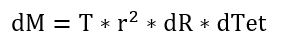
here r is distance to axis while dR, dTet are radius and angle differentials respectively. By integrating the elementary moment over the contact area one obtains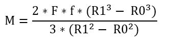
This expression relates applied torque, M, and axial force, F.
Axial force depends on the structure and bolt stiffness, and on nut displacement relative to the bolt: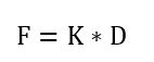 here K is structure stiffness factor, D is relative displacement. Relative displacement can be expressed through nut turns as
 here N is number of turns, H is thread pitch. Therefore,
 Let us assume that at first analysis pass one nut turn is prescribed N(1)=1, and corresponded axial force F(1) is found from the analysis.
Then one can find structure stiffness factor as: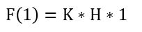
which implies: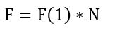
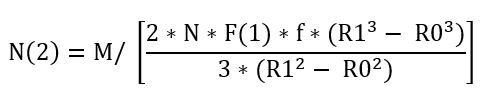
Now we can relate torque to number of turns: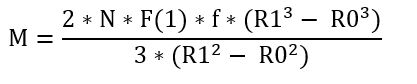 Therefore, in order to realize prescribed torque M, after the first analysis is done with N=1, second analysis (second convergence pass) must be performed with:
In general, at pass (i + 1) the number of turns applied is: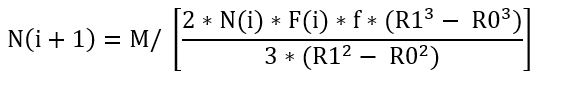
where N(i) is number of turns applied at previous pass, and F(i) is result axial force evaluated at previous pass. These corrections for number of turns applied are important because in the course of passes solution is refined, which changes structure stiffness factor K in equation A above. So, K is not constant, but depends on pass K(i)
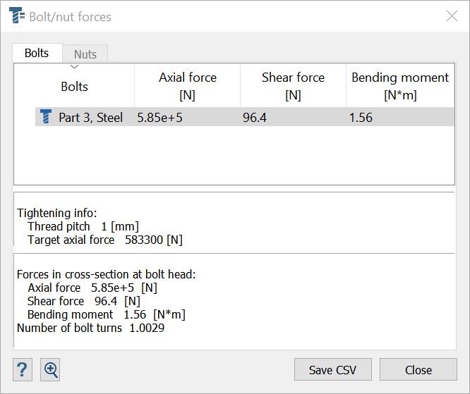
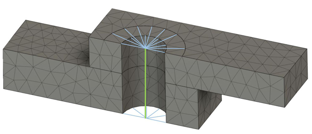
Figure 1: Common bolt representation in conventional FEA
The load path in this case is as follows: part 1 > spider 1 > bolt beam > spider 2 > part 2. A beam representing the bolt shank is loaded at the end nodes only. Therefore, in case there is no moment at the beam ends, the beam is under pure axial loading and has uniform axial stress along its axis. Note that this bolt tightening value and distribution is obtained under huge modeling assumptions.Bolt tightening
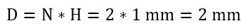
In real world, when a bolt is tightened, it elongates. Let us consider the following example. A bolt with a nut (Figure 2) connects two absolutely rigid parts A and B. Let us assume that the thread pitch (Figure 3) is equal to H = 1 mm.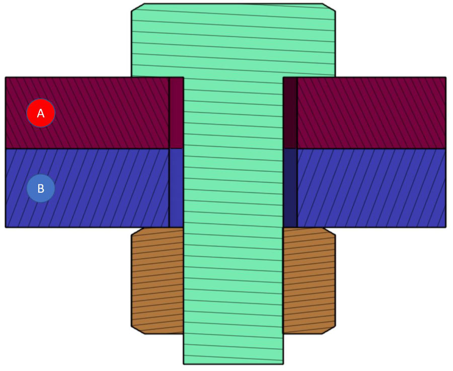
Figure 2: Cross section of bolt with nut clamping two parts
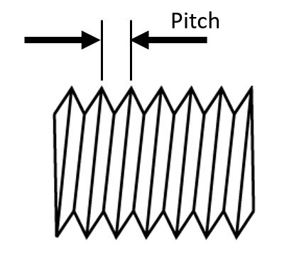
Figure 3: Definition of thread pitch
Then, if the nut makes two turns during bolt tightening, N = 2, it must pull the bolt shank out onto the distance equal toThis distance is the bolt elongation. If parts A, B are not absolutely rigid, the elongation will be less than 2 mm because the parts are squeezed and will deform.
Bolt tightening in FEA
In conventional FEA bolt tightening is always simulated via prescribing bolt shrinkage. Bolt shrinkage is set by many different modeling techniques - via negative temperature change, initial strain, relative displacements of the bolt beam element, material removal from the bolt shank, etc. But no matter which technique is used in conventional FEA, tightened bolt shrinks, not elongates. Which actually contradicts the physics, but it works in terms that it provides the source of the tightening load.Bolt tightening in Altair SimSolid
Altair SimSolid always simulates bolt as a full solid with all the geometrical details. A bolt is connected to other parts at bolt head and at bolt shank. Stresses in bolt are described by a full 3D stress tensor.Bolt tightening is realized as it occurs in real world - by defining displacement of a nut or part (in case bolt has no nut) relative to the bolt shank. In the example (Figure 2) this is 2 mm displacement. For user convenience, instead of prescribing total relative displacement, one only needs to enter thread pitch H and number of turns in the force input dialog.
There are substantial differences in stresses obtained from 1D FEA and 3D Altair SimSolid models of the bolt. Let us consider a bolt above (Figure 2).
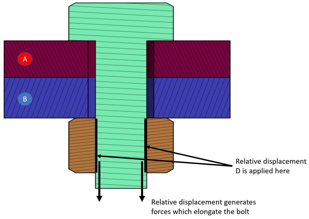
Figure 4: Bolt tightening in Altair SimSolid
The relative displacement D of bolt shank with respect to the nut is applied at bolt threads which are in contact with the nut. These displacements generate a significant shear forces applied to bolt threads. The forces pull the bolt down, elongate the bolt, and eventually translate into bolt axial stress and axial force.In a 3D model, the bolt axial stress is never uniform – neither along the bolt axis nor in a cross-section of the shank. Theoretically, it must equal zero at the end of bolt. It reaches maximum at the portion of the shank beyond the bolt threads.
In Altair SimSolid, tightening loads can be applied to a variety of geometries, including blind bolts, bolts with nuts, nuts on threaded rods and nuts on a generic post or handle. Bolts are automatically identified by their geometric attributes. Bolts are required to have cylindrical bodies and a head with a hexahedral based shape. The hex shape can be on an outer or inner diameter in the bolt head. Nuts are identified in a similar manner using this hex based geometric signature.

Figure 5: Inside hex head bolt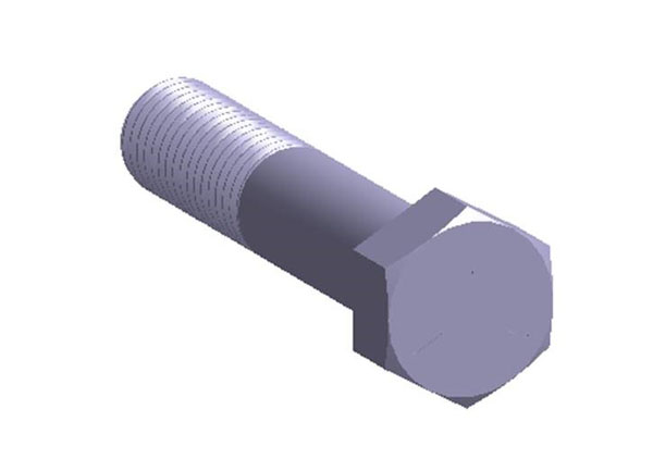
Figure 6: Outside hex head bolt
Three methods are available to specify bolt/nut tightening loads:- Bolt turns
- Bolt Torque with friction
- Target axial load
Warning, gory technical details follows
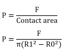
Torque M and axial force F relate to each other in the following way. M is the maximum moment realized at the end of the tightening and it is equilibrated by moment from friction forces in contact between nut and the structure.Let us assume for simplicity that normal forces in contact are distributed evenly, so the contact pressure is:
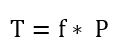
here R0 and R1 are inner and outer radii of contact spot. Friction distributed force will be:
where f is a friction coefficient. In polar coordinate system, the elementary moment of the friction force with respect to the bolt axis is:
here r is distance to axis while dR, dTet are radius and angle differentials respectively. By integrating the elementary moment over the contact area one obtains
This expression relates applied torque, M, and axial force, F.
Axial force depends on the structure and bolt stiffness, and on nut displacement relative to the bolt:
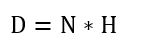
here K is structure stiffness factor, D is relative displacement. Relative displacement can be expressed through nut turns as
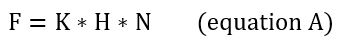
here N is number of turns, H is thread pitch. Therefore,
Then one can find structure stiffness factor as:
which implies:
Now we can relate torque to number of turns:
Therefore, in order to realize prescribed torque M, after the first analysis is done with N=1, second analysis (second convergence pass) must be performed with:
In general, at pass (i + 1) the number of turns applied is:
where N(i) is number of turns applied at previous pass, and F(i) is result axial force evaluated at previous pass. These corrections for number of turns applied are important because in the course of passes solution is refined, which changes structure stiffness factor K in equation A above. So, K is not constant, but depends on pass K(i)
Now back to our regularly scheduled program
Wow, that was way too many equations. The good news is only the very curious will need to look at them again. One point to make though is that from these equations you can see that the prescribed Torque or Axial force are target values and may not be achieved exactly during the iterative process.Bolt tightening example
To examine this in more detail, let’s look at an example. Here (Figure 7) is a blind bolt (green) connecting two plates (red and blue).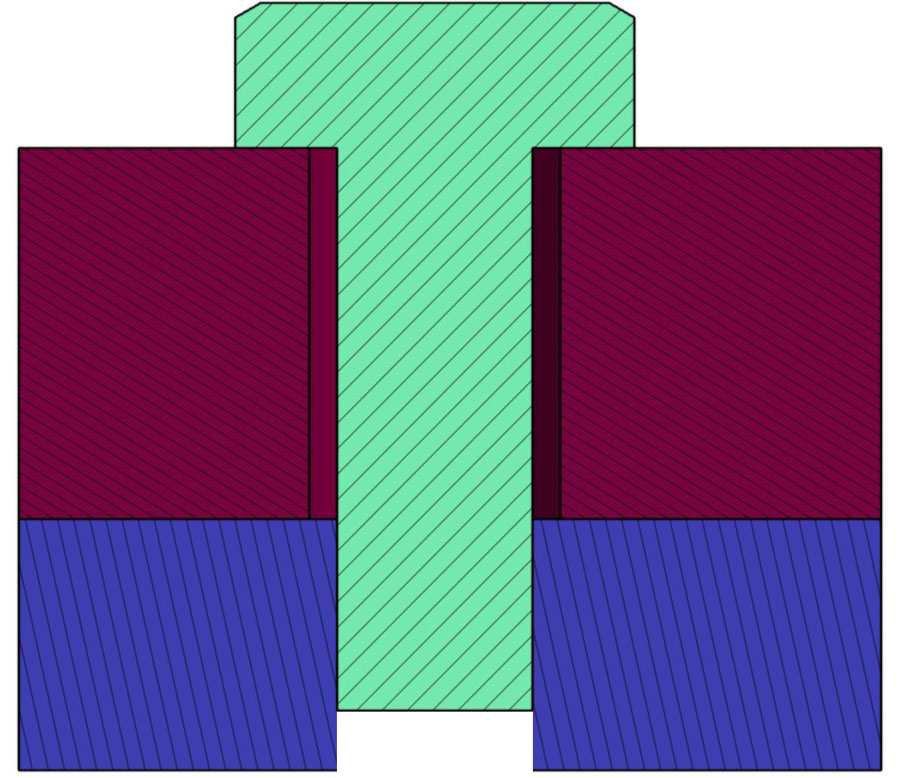
Figure 7: Blind bolt cross section
We will use two of the three methods to create the tightening load and examine the results. First open the Bolt tightening load dialog (Figure 8) and use the number of turns method. For simplicity, let’s assume 1 mm thread pitch and 1 complete bolt turn.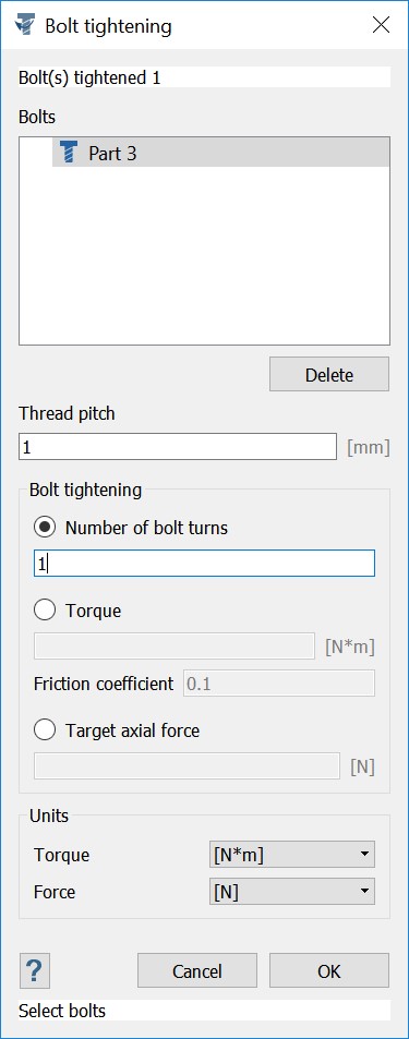
Figure 8: Bolt tightening load dialog
Once the analysis is complete, open the Bolt/nut forces dialog ( Figure 9) and examine the bolt forces results. We see a large axial load of 5.833e+5 N.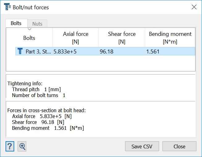
Figure 9: Bolt forces for Number of turns loading
Now, let go back and do the analysis again, but this time specify a target axial force of 583300 N. With standard solution settings, the achieved axial force, 5.85e+5 N, is very close to our target (Figure 10) and notice that that the equivalent number of bolt turns is 1.00. We got to the same result but used two different input methods. Which method to use is a matter of choice. What is important is that Altair SimSolid provides full 3D bolt tightening without all the 1D assumptions typical in conventional FEA.
Figure 10: Bolt forces for Target axial force loading