Changing the Way Antennas Are Designed using CMA
Why are antennas so important? Basically, because they are “the eyes” of any wireless, communication, navigation or radar system. The antenna determines the coverage of a system, for instance, whether you will be able to lock or unlock your car from any direction. An antenna for a mobile phone has to be designed while considering the effect of the head and hands when the user holds the phone. Otherwise, the number of dropped calls can increase significantly. Also, a bad antenna design can tremendously reduce the battery life of on an Internet of Things (IoT) device. These are some of the reasons why the number of innovations on the antenna field has been growing during the last 15 to 20 years.
The mobile phone industry is one of the industries that has seen an amazing growth. The number of mobile phones has increased 1700% since 2000. In fact, even before 2000, mobile phone manufacturers were heavily investing in new innovations, like Nokia 8810, which was the first mobile phone with internal antenna that was launched in March 1998.
Highlights on How Antenna Design Has Changed
In the early 2000s, I was involved in antenna design for mobile phones, and most phone manufacturers were not really thinking of the antenna during the early stages of the design phases. Many of them were reserving a certain volume at the top (or bottom) of the phone for the antenna, and then providing such information to suppliers to design the best possible antenna in that limited volume. Nowadays, the situation has changed. Cell phone manufacturers are thinking much more about the antennas during the early stages of the product design. This change is also related to the increasing amount of services on a phone, such as cellular, Bluetooth, WiFi, GPS and NFC, and such trend has allowed more antenna innovations. Antenna engineers are looking for new locations to integrate the antennas while taking advantage from metallic elements on the devices. If you search for antenna patents or patent applications, you will easily find many recent documents related to antennas for electrical devices with conductive housing, chassis-excited antenna or antenna integrated with metal chassis, and more.
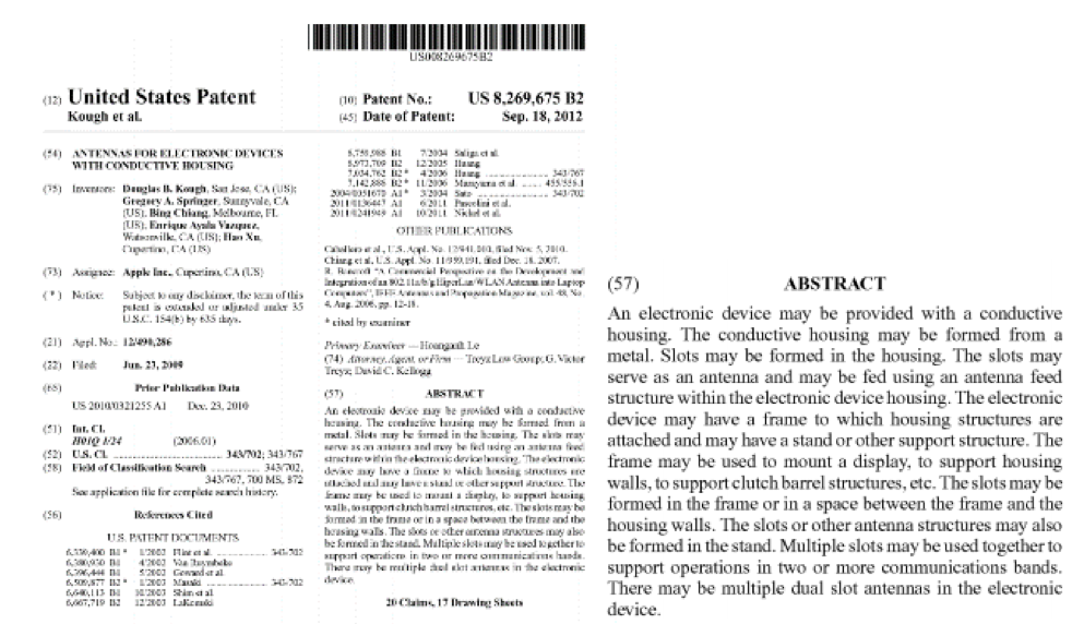
United States Patent related to antennas for electronic devices with conductive housing.
If we talk about the placement of antennas in bigger structures or platforms like cars, ships, aircraft or helicopters, in general, antennas are typically placed at the same locations; however, the developers of such platforms are continuously looking for new approaches to improve the performance of the antennas in the system. The antennas hidden in the rear windscreen of a car are an example of innovation where more and more antennas are being integrated, including antennas for services like analog and digital radio, TV or remote key-less entry systems.
What Is and Why CMA?
While using electromagnetic simulation tools, engineers working on antenna design and placement are looking for smart solutions to use systematic, non-brute force, design approaches. This is where CMA (Characteristic Mode Analysis) comes into play.
CMA is the numerical calculation of a weighted set of orthogonal current modes that are supported on a conducting surface. With CMA, you can know which are the possible currents (or modes) naturally supported by the structure - something extremely useful to gain physical insight on how the structure is radiating. In other words, from an analysis point of view, by applying CMA you can better understand how your antenna works and how efficient is your design. On the other hand, from a design point of view, you can know which are the best locations for the antenna and how to excite the antenna using a more systematic approach.
Finding the Best Location for the Antennas on a Mobile Phone
A leading company designing and manufacturing antennas for mobile phones contacted us with an interest in finding a solution to more efficiently and cleverly find the best location for the two 4G cellular antennas on a cell phone in a Multiple-Input Multiple-Output (MIMO) configuration. One of the challenges was that the antennas should be as independent (isolated) as possible, so to achieve the desired data rates provided by 4G.
Thanks to the CMA feature in FEKO, the modes of the main board of the phone were calculated first without including any antenna. It showed that the first 2 modes (1 and 2) were the ones: (a) contributing more to radiation, and (b) featuring the current distributions leading to the desired radiation patterns (or coverage). Afterwards, by analyzing the currents provided by CMA further in detail, each one of the antennas was strategically placed on the main board in order to excite modes 1 and 2 respectively. By using CMA when compared to a traditional approach, we could get a design where the antennas were much more isolated one with respect to the other.
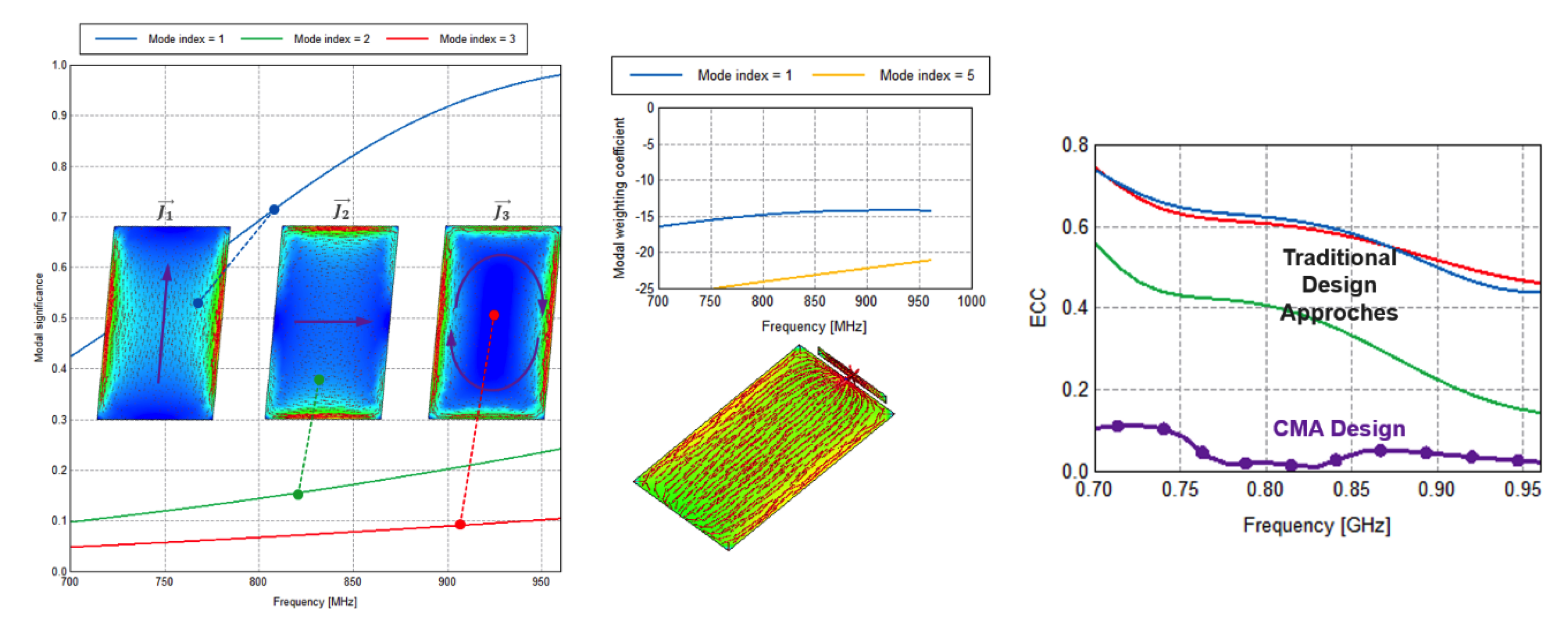
Computed current distribution for first three modes of cell phone main board (left), graphs showing placement of one of the two antennas being mode 1 the main mode (middle), comparison of isolation against frequency for different antenna designs – lower is better (right)
CMA in the Market
CMA was originally proposed in 1970s by Garbacz, and then afterwards refined by R.F. Harrington and J.R. Mautz. Innovation has been in FEKO’s DNA since many years ago, and for that reason, direct support for CMA was included in FEKO in September 2012, and became the first commercial electromagnetic simulation software to offer CMA. In fact, even before 2012, FEKO had indirect support for CMA for quite a long time as well.
Over the years, the number of FEKO users taking profit from CMA has been significantly increasing in many industries, while CMA in FEKO continues to become more powerful and reliable. Moreover, another CMA case in the automotive industry is the calculation of the modes of a car. With such information, you can search for better alternative locations to place the antennas depending on the desired coverage, and also define strategies on the best way to excite such antennas.
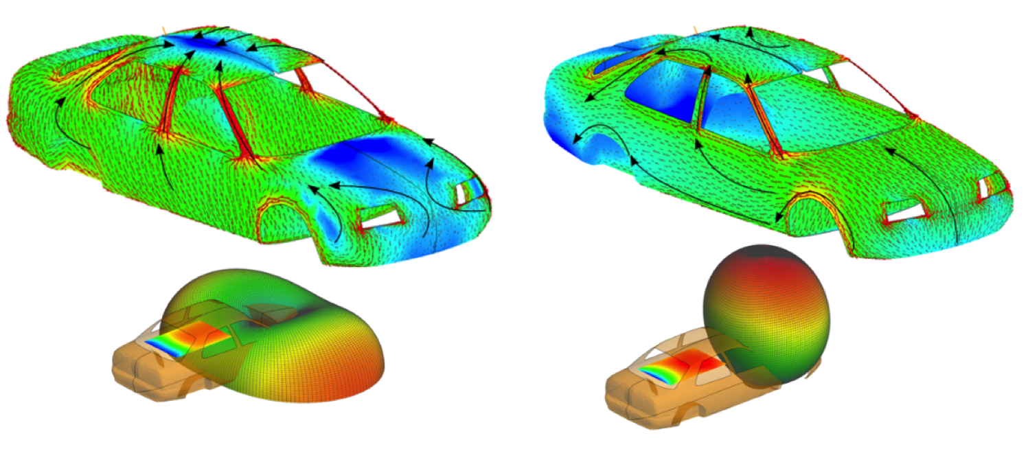
Computed current distributions and related radiation patterns for the first two modes of a car using CMA.
Last year, some of the companies and universities whom attended the Altair Technology Conference 2015 held in Paris presented their works and achievements using FEKO’s CMA.
On the academic side of the market, CMA is also gaining a great momentum. Last year at the EuCAP’2015, the largest antenna conference in Europe, the sessions related to CMA were completed packed, many universities worldwide are now using CMA in FEKO for antenna design and placement. Finally, it is definitely worth mentioning that the 11th annual FEKO Student Competition winner was Mr. Ting-Yen Shih with an amazing entry related to CMA.
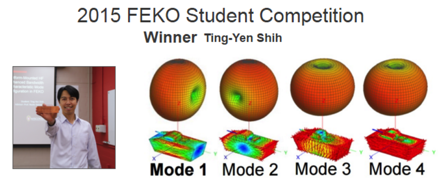
Winner of the 2015 FEKO Student Competition with entry entitled “Design of Platform-Mounted HF Antennas with Enhanced Bandwidth Using the Characteristic Mode Configuration in FEKO."
CMA Trends – Today and Future
We are seeing how CMA in FEKO is helping the industry and universities to take antenna innovations further while providing a systematic and non-brute force approach to better understand the behavior of antennas, and to know how efficient an existing design is and how it could be improved. CMA can assist in defining the best approach to excite an antenna alone, or when mounted on a platform to achieve the desired performance.
In the future, we will see the number of cases and applications for CMA grow not only on the antenna field, but also on other applications like Electromagnetic Compatibility (EMC).
To know more details about CMA, watch this webinar recording. Please feel free to get in touch with us, and let us show you how to take benefit from CMA in FEKO!