
Thought Leader Thursday: Five Common Mistakes made Running Topology Optimization
Topology optimization is an approach that optimizes the material distribution within a given design space, for a given set of loads and boundary conditions, to meet a set of performance targets. Using topology optimization at a concept level can help you achieve the best performing design while saving time by replacing costly design iterations.
Is it really that simple to find a concept design though? It could be, if you properly use the technology Altair offers in tools such as OptiStruct and solidThinking Inspire to your benefit. Just like any other mathematical program, when used incorrectly topology optimization can also lead to poor designs. Let’s look at some of the common mistakes made while running topology optimization for the first time:
Not defining the proper design space
Topology optimization is done at a design concept level after the product’s packaging spaces are identified. Ideally you want to use all the available packaging space as your design space as it has the greatest potential to give you the most optimal concept design. However it might not be possible to do so all the time. One of the factors that needs to be considered while creating design space from the packaging space is human and/or tool accessibility during manufacturing, assembly, and maintenance.
An existing design is not a good package space to use for topology optimization. An existing design already has a material layout defined and so it is unlikely that it will yield to an optimal concept design.
Let’s try to understand this with the below example, the pictures shown are that of a bike rocker arm. Comparing the designs at the bottom, we can see that design freedom plays a major role in finding optimum load paths, thereby leading to a better performing design. ‘Design 2’ is 25% stiffer than ‘Design 1’ for the same amount of retained mass.

Not identifying non-design space
After defining the design space from the available packaging space, it is also important to identify the non-design space. Regions in the model that cannot be modified during the course of the optimization are the non-design spaces. These are typically the connection points that connect to other components in the system or simply regions that need to exist for proper functioning of the system. These non-design spaces need to be identified beforehand to get a design that satisfies all the assembly constraints.
Over-constraining the model
Just like us humans, topology optimization works best with enough design freedom. Having too many performance constraints included in the optimization formulation limits the optimizer from exploring the design space. Let’s try to understand that with an example. While running topology optimization, it is not wise to have constraints on stiffness, strength, stress and frequency concurrently, instead let strength targets drive your concept design, while fine tuning techniques can be used to achieve other performance targets. The optimization formulation is one of the most important factors to consider in order to get a good conceptual design.
Not having a fine enough mesh
Topology optimization results are mesh dependent, i.e., the design obtained on one mesh may not be the same as the design obtained on a different mesh, so not having a fine enough mesh may not result in a useful design. Some of the features of the design become more intricate with a refined mesh. In OptiStruct, it is recommended to choose an element size such that there are at least three elements along the smallest dimension of a manufactural member.
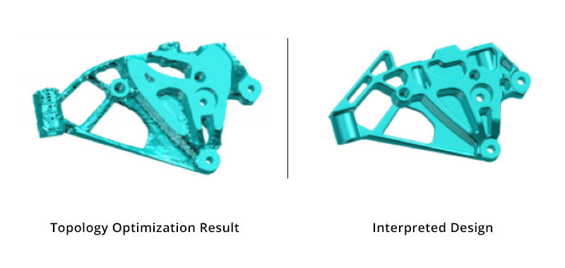
Forgetting that topology result is not the final design
Topology optimization is meant to give you the direction required to design a component, it does not design the component for you. It tells you where the material is required to meet your performance targets. The results obtained from topology optimization need to be interpreted by the designer taking into account factors such as cost, time, and manufacturing feasibility. Interpretation includes, but is not limited to, adding detailed design features as fillets and chamfers, removing sharp corners, merging multiple smaller members to form one large member, etc. The picture below shows an example of how topology optimization results have been interpreted by engineers at Volkswagen to design an engine bracket.
 Now that you are aware of some of the mistakes to avoid while running topology optimization; I hope you will be more comfortable while using it in the future.