
Why CAD-based Simulation Can Become a Game of Cat and Mouse
Like a cat sitting in front of a mouse hole, we’ve often found ourselves sitting in front of our FEA analysis, waiting for a result and asking ourselves, ‘what’s going on in there?'
We recently heard a similar analogy from a design engineer who develops industrial machinery equipment. Many design engineers face similar challenges navigating finite element analysis (FEA) modules within their computer-aided design (CAD) tools, which are notorious for being somewhat of a black box. Like the cat peering through the mouse hole, designers can struggle to determine what’s going on behind the scenes, and importantly, what can be done to improve the accuracy and simulation run times of their models.
Overcoming Modeling Gaps Between CAD and Simulation
CAD and FEA modeling have some fundamental differences that can present hurdles between design and analysis. In many 3D design and CAD applications, especially when designing machines, the CAD drawing must be created with tight tolerances. For part manufacturing, accurate tolerances are a crucial part of the design, sometimes requiring precision down to microns. But whether you make your design in SolidWorks, Solid Edge, Creo, Siemens NX, Catia, Inventor or another CAD software, analysis within these design tools can be limited.
Every CAD-based or automated simulation solution must make assumptions to complete the initial geometry representation with all the necessary details that are required to let the simulation run and predict the parts, assembly, or product behavior. Often, the automation of CAD-based simulation model creation doesn’t always make the right decisions to create a meaningful, realistic model. So, design engineers find themselves waiting longer than desired for results during the modeling process. CAD-based simulation presents the most basic version of the design’s performance, often not considering the details and specific physics like interactions between parts, connections, frictions, and material behaviors that need to be represented in the simulation to give meaningful results in a timely manner.
As an example, consider a simple press fit with two components being joined together. If for instance, a modeled shaft was slightly larger than the sleeve, in CAD both parts would be represented in their original dimensions. If the dimensions are even slightly off, it would be enough to give your simulation trouble when relying solely on CAD.
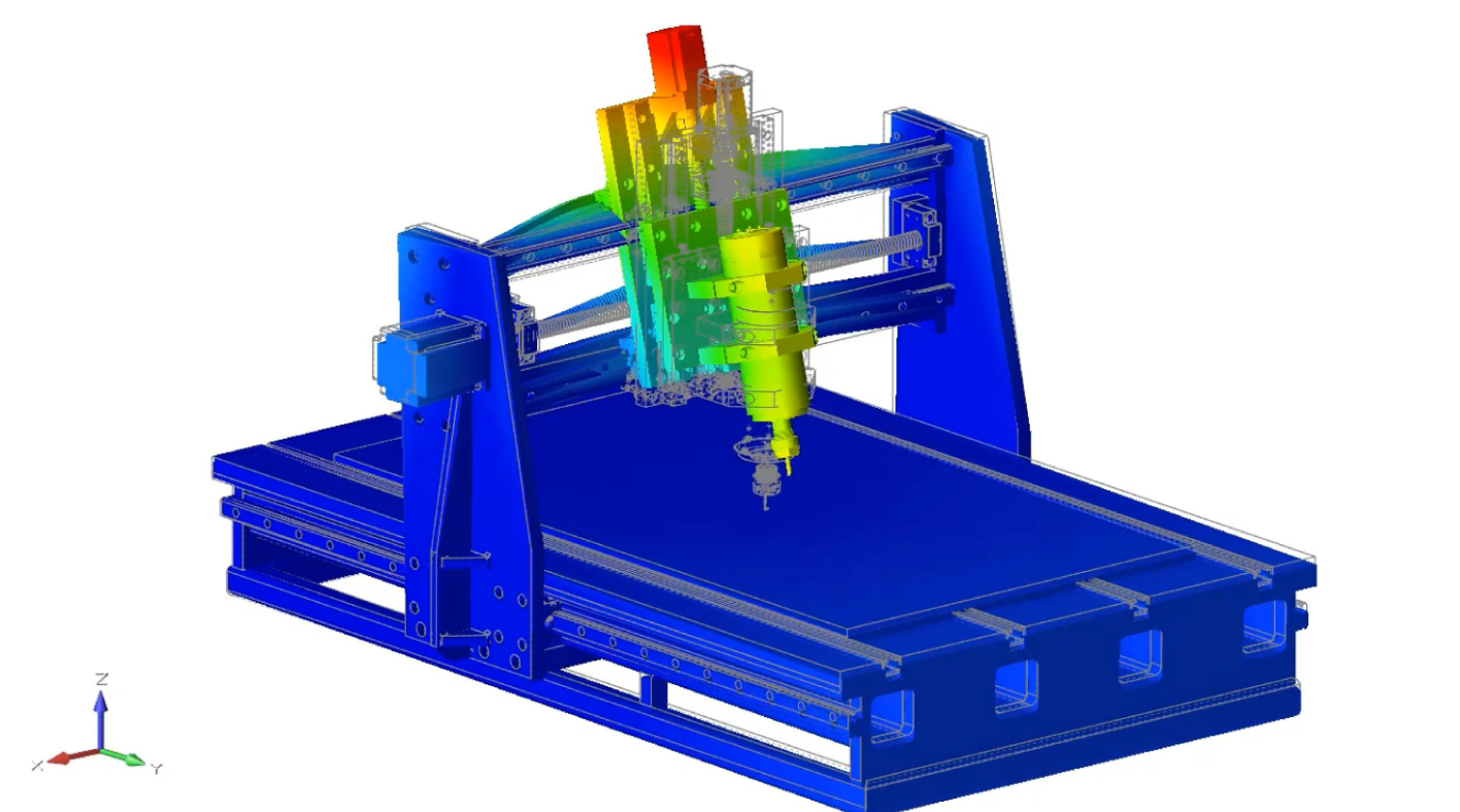
Accuracy in this scenario becomes even more jeopardized when a model has multiple and/or moving parts, with full flexibility and different types of motion. When considering all of these factors, it’s easy to see how the wrong approach to part analysis can cause a big divergence between the simulation and what you might see in a test or a physical setup.
This is just one instance where CAD-based simulation may not be enough to support the full geometry of a design that a user is looking to analyze in their software. Many of the minute details of a CAD drawing are not necessary for simulating physics with FEA, and their presence in the model can slow down solve time and even lead to less accurate results.
Use Simulation for More Actionable Results with Meaningful Models
This is where the value of a comprehensive simulation-driven design approach really materializes for design engineers - modeling and prediction of part behavior can be produced more accurately, as model features and fidelity can be modified to fit the needs of a particular analysis. By importing CAD into CAE-centric analysis software, the user gains more control over the accuracy and speed of analysis.
Intuitive surface modeling and geometry modification tools in Altair Inspire™ help users prepare models for analysis quickly at the fidelity that best suits the analysis detail and solver performance needed at that stage of the development process. This ensures that iteration and comparative studies are possible in early-stage design while offering the flexibility to model at higher fidelity for performance validation and detailed physics assessments.
With tools like Altair SimSolidTM, a solver available within the Altair Inspire product, users can import intricate CAD geometries and assemblies, including connections, contacts, welds, detailed dimensions and angles, and more without model simplification or modification. And this highly accurate solver produces results in seconds to minutes, enabling multiple concepts to be assessed in less time than one typical CAD-based simulation run.
Performing more detailed multiphysics analyses including structural, thermal, and fluid dynamics is easily attainable with Altair SimLab™. It’s intuitive user interface enables geometry to be imported and updated via the bi-directional CAD coupling. This way, there’s no questioning how the process automation within your software is performing because the tool is fully interactive with the ability to perform work directly on geometry.
Faster, More Reliable Insights from Simulations
The best way to improve simulation speed and accuracy is to use the right model, for the right decision, at the right time. CAD models are ideal for producing accurate manufacturing drawings, but FEA is more adept at modeling a product’s realistic behavior. FEA tools that allow design engineers to select and tune their model fidelity based on the needs of the simulation help to further improve solver speed and accuracy.
Click here to see how simulation-driven design with Altair enables a complete design workflow for industrial machine design.
Simulation software like Inspire works with existing CAD tools, so pre-existing models can be easily imported into the software for geometry modification and analysis. To get the most detailed results from your CAD model, in Inspire users can utilize trusted Altair solvers such as SimSolid for running finite-element analysis (FEA) on designs, Altair MotionSolve™ for motion simulation, and Altair OptiStruct™ for performing topology optimization.
Having full visibility into your design tools is the key to addressing multiphysics problems with both speed and confidence. Learn more at altair.com/inspire or click below to read about the digital transformation requirements for the industrial machinery sector.