
Lay-Up Simulations to Choose the Best Fabric Pattern for an Aeronautic Radome


This guest contribution on the Altair Blog is written by the Cedrem Team. Cedrem is a member of the Altair Partner Alliance.
Antennas can be found in various fields, from very common applications such as cars, planes, communications or weather stations, up to very specific ones such as missiles or military vehicles.
The present article focuses on weather radars mounted on small airplanes. They help planning routes before take-off and adapting during the flight depending on weather conditions. They are usually mounted in the airplane nose or on a wing and protected
by a radome. 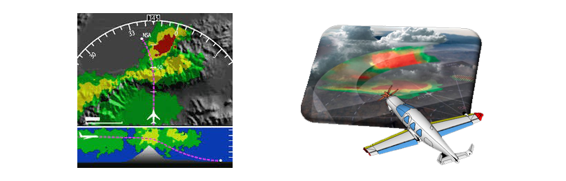
Pictures from Altair
These radomes must face a triple challenge consisting in ensuring enough mechanical resistance to protect the antenna from external threats (hailstones, birds, lightning …), offering electromagnetic passivity in order not to disturb the radar operation and respecting aerodynamics conditions. These objectives are often in contradiction as mechanical resistance increases with the thickness and the stiffness of the radome, whereas the electromagnetic passivity decreases in the meantime.
In order to enlighten the radomes without decreasing their mechanical resistance, composite fabrics have been investigated. They offer interesting mechanical properties combined with good electromagnetic passivity. But as they are orthotropic material, their manufacturing process can impact the electromagnetic performance of the antenna. Also, different weaving patterns could provide the same mechanical resistance but provide different electromagnetic performance.
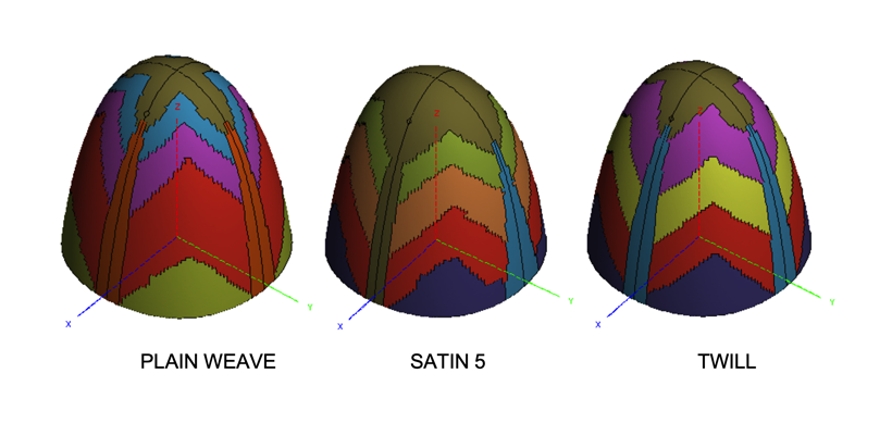
The aim of this study is to simulate the laying-up process of a radome with different weaving patterns, assign different electromagnetic properties depending on the results, and perform an electromagnetic study of the different configurations. The analysis will lead to the best configuration choice. The considered fabrics are a plain weave, a satin 5 and a twill. The lay-up simulations were performed with KTex Family and Altair Radioss™. The electromagnetic simulations were performed with Altair FEKO™.
The first step is to represent the different fabrics at the scale of the yarns (meso-scale). This step is mandatory to see the effect of the manufacturing process on the orientation of the fibres. Based on the weaving patterns, the mesoscopic models of the different fabrics were built with KTex Pattern
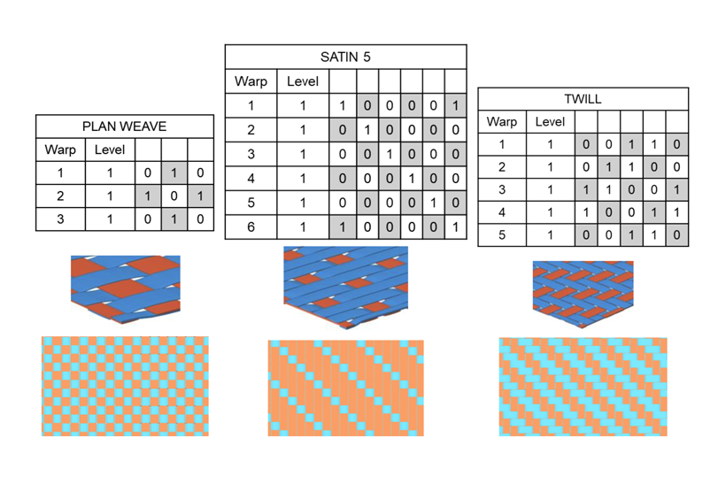 The next step is to simulate
the laying-up of these fabrics on a radome shape. This was done using KTex LayUp. The radome shape was an input from Altair and the simulation was run with RADIOSS.
The next step is to simulate
the laying-up of these fabrics on a radome shape. This was done using KTex LayUp. The radome shape was an input from Altair and the simulation was run with RADIOSS.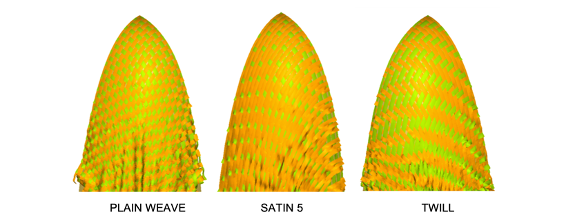
A visual analysis of these results can lead to building customized models of radomes, gathering the fibres with the same orientation in a same component.
The electromagnetic results can be compared with a perfectly oriented radome. First, some investigations have been made to see if the 3 fabric configurations respect the DO213 standard in terms of side lobes level. The table below shows the allowable side lobes level highlighted in the DO213 standard.
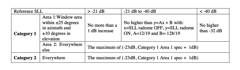
DO213: allowable side lobe level vs radome category
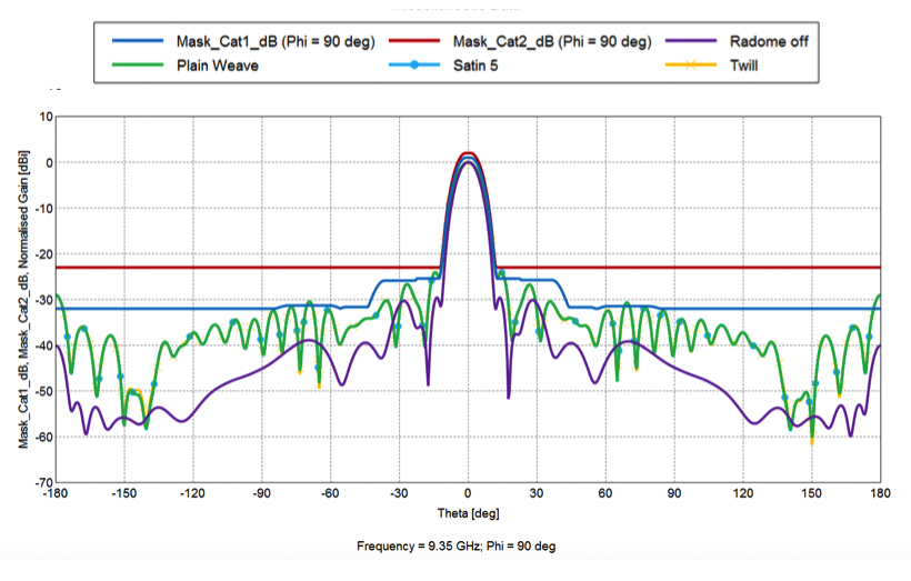
Far field patterns for Alpha=0° and Beta=0°
Far field patterns for Alpha=-20° and Beta=-10°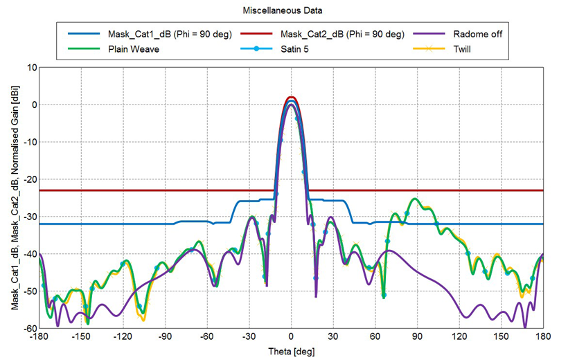
Far field patterns for Alpha=-30° and Beta=-20°
We made investigations on 3 different radar positions with nominal and extreme positions and compared the antenna patterns to the limits highlighted in the DO213. Alpha is the scanning
angle in the azimuth plane and Beta for the elevation plane. One can note that, from these investigations, the 3 radome configurations respect the Category 2 standard level.
Additional investigations were made over all the scanning range and we compared the side lobes rejection for the radome configurations. One can notice that the side lobes rejection is better for the Satin 5 and the Plain weave fabrics, whereas the Twill
gives worse side lobes rejection. This shows that the Twill is on the threshold level for the side lobes rejection. Adding the lightning stripes can degrade significantly the patterns. As an alternative, the discontinuous stripes (diverter stripes)
can be used for less FF pattern degradation in terms of side lobes level.
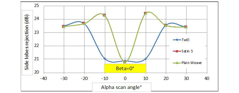
Side lobes rejection for Beta=0°
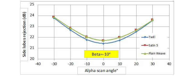
Side lobes rejection for Beta=-10°
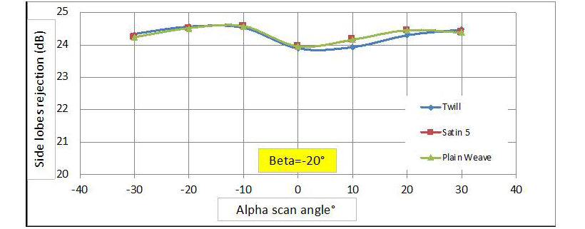
Side lobes rejection for Beta=-20°
Many other electromagnetic simulations could be performed to compare the different fabrics when considering the final integration on the airplane.

Pictures from Altair
In conclusion of this study, different fabrics were represented with KTex Pattern and laid-up on a radome shape with KTex LayUp. The results were manually transposed into FEKO to perform electromagnetic simulations. The results of these simulations helped in comparing the different fabrics and their impact on antenna pattern. However, some future work could be imagined to create a more powerful and effective workflow.
ement model output from KTex LayUp into a sorted macro-scale model into FEKO. An intermediate step would be to automatically map the orientation of the fibres and the thickness of the fabric of the manufactured fabric onto a macroscopic model of the final shape in HyperMesh. This could then be exported into FEKO. Such an automated process would greatly decrease the time needed to analyse the KTex LayUp results, and would also ensure the repeatability of the analysis, which is today based on the user interpretation.
Another improvement could be to take into account the weaving patterns in FEKO. Today, orthotropic electromagnetic properties can be set-up. But a fabric has the same properties as 2 shifted unidirectional plies on top of each other. Maybe the influence of the weaving pattern could be taken into account somehow.
Finally, the transposition of such complex HyperMesh models into FEKO could be done automatically. Some translators could probably be developed to save time and avoid translation mistakes.
Learn more about KTex by Cedrem available through the Altair Partner Alliance

