
The Curse of the Split Melt
This guest contribution on Innovation Intelligence is written by Håkan Fransson, CEO at NovaCast Systems AB, developers of NovaFlow&Solid CV. NovaCast is a member of the Altair Partner Alliance.
It may not be 100% correct, but I once said that there is not one single casting part in Sweden that is fully optimized for the casting method. That can also be said for Europe and the rest of the world. Most of the time, the casting products are designed without consulting a foundry or someone with deep foundry technology expertise. In recent years, the aim for structural optimization has increased, with OptiStruct for example. Applying casting process simulation as well as a higher will to optimize castings for the process may improve the situation. The 100% optimization of a casting may not be realistic, due to the complex nature of the casting process, but I can say with certainty that more than 90% of all castings in the world are not fully optimized.
This article will provide insight on how to solve this issue. “The Curse of the Split Melt” refers to one of the most crucial key factors to address in a casting part. A split melt causes islands of melt where there are hot spots. These hotspot islands cannot always be reached by feeding or cooling, which means that they are not part of a directional solidification. Those islands are the cause for the shrinkage defects in casting. By following some basic ground rules you can prevent most of these problems:
 There are distinct split points where the arrows are placed. It looks good but the angle of the metal front is too blunt, it should be pointed. The metal front should look like an arrow with a sharp edge. The inner angle of the arrow should be small to make sure that there is no risk that the melt divides in small islands.
 Wrong metal front
 Correct metal front
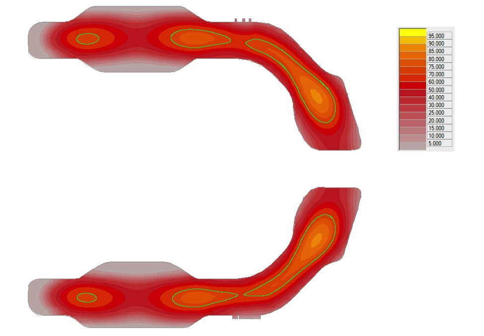
The circle shows a hot spot area which is hard to feed or chill. The risk for shrinkages in the heat center is high.
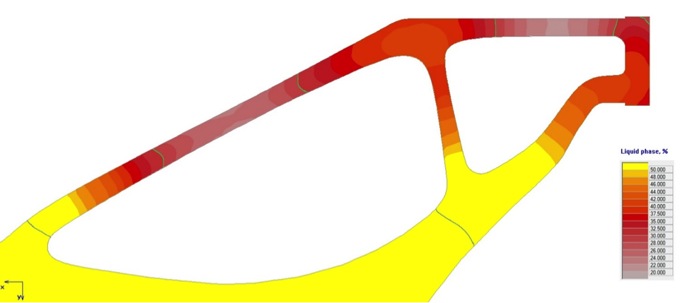
 This is an example of a casting where there is serious splitting of the melt. This will cause shrinkage defects. Using some simple design rules when designing the casting will result in a more directional solidification and also define distinct splitting points.
In general, the foundry should not have to use “duct tape” to be able to produce a proper casting. The casting should be designed for the casting process. Once the part is ready for production in the foundry, adjustments for the casting process can only be made to a certain extent. This must take place as early as possible. The component should be seen as a casting already from day one, not only as a functional component.
The 90/10 rule is also something to consider – it applies if you produce good design work from the start. Much less time needs to be spent making correctional measures. My advice is to spend a lot of time in the beginning to get an easy production start of the casting.
I have heard many say that the casting quality is up to the foundry to ensure, but I think it is the design engineers that really create the possibility to make a sound casting without defects. I have seen that more and more companies have started to work like this but I hope for an increasing number. By applying the rules above you will save material, energy and money, and in the end this will be good for our inner and outer environment in the foundries and also the world.
It may not be 100% correct, but I once said that there is not one single casting part in Sweden that is fully optimized for the casting method. That can also be said for Europe and the rest of the world. Most of the time, the casting products are designed without consulting a foundry or someone with deep foundry technology expertise. In recent years, the aim for structural optimization has increased, with OptiStruct for example. Applying casting process simulation as well as a higher will to optimize castings for the process may improve the situation. The 100% optimization of a casting may not be realistic, due to the complex nature of the casting process, but I can say with certainty that more than 90% of all castings in the world are not fully optimized.
This article will provide insight on how to solve this issue. “The Curse of the Split Melt” refers to one of the most crucial key factors to address in a casting part. A split melt causes islands of melt where there are hot spots. These hotspot islands cannot always be reached by feeding or cooling, which means that they are not part of a directional solidification. Those islands are the cause for the shrinkage defects in casting. By following some basic ground rules you can prevent most of these problems:
1. Use casting process simulation to understand the complexity of the solidification.
The human brain may understand a two dimensional solidification but a third dimension creates more or less a shorting in our brain if we even try to understand the complex correlations. Today the casting process simulation is highly reliable and gives very good results.2. Define where you want to have controlled split of the melt.
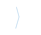
The casting designer should, in principle, define splitting places in the design stage and design the part from this criteria to reach a directional solidification. This is the only way to avoid shrinkages completely, and is also a way to avoid more feeders than are absolutely necessary. The split points should be a design constraint with the same weight as a design constraint of functional art. There are distinct split points where the arrows are placed. It looks good but the angle of the metal front is too blunt, it should be pointed. The metal front should look like an arrow with a sharp edge. The inner angle of the arrow should be small to make sure that there is no risk that the melt divides in small islands. Wrong metal front Correct metal frontThe circle shows a hot spot area which is hard to feed or chill. The risk for shrinkages in the heat center is high.
This is an example of a casting where there is serious splitting of the melt. This will cause shrinkage defects. Using some simple design rules when designing the casting will result in a more directional solidification and also define distinct splitting points.3. Decide where the feeders should be placed in the design phase.
Prepare the placement to minimize cutting and grinding and save energy and time.4. Do not use chills.
Chills create a high temperature gradient in the localized areas where they are placed. This increases the risk for cracks a lot because of the different solidification times in comparison with the mold material. The cracks will not occur where chills are placed, instead in between the chills. Chills also increase the complexity of the solidification pattern and can be counterproductive to achieve a directional solidification. The chills also change the microstructure in the localized areas, which can then change the strength of the material.5. Pattern maker allowance and tapers should be designed from the start.
The simulations need to be made in correct section sizes and volumes, and the taper and pattern maker allowance must be defined. If this is not taken into account from the beginning, all changes made to achieve a directional solidification can be eaten up by the changes that are necessary to make later on.In general, the foundry should not have to use “duct tape” to be able to produce a proper casting. The casting should be designed for the casting process. Once the part is ready for production in the foundry, adjustments for the casting process can only be made to a certain extent. This must take place as early as possible. The component should be seen as a casting already from day one, not only as a functional component.
The 90/10 rule is also something to consider – it applies if you produce good design work from the start. Much less time needs to be spent making correctional measures. My advice is to spend a lot of time in the beginning to get an easy production start of the casting.
I have heard many say that the casting quality is up to the foundry to ensure, but I think it is the design engineers that really create the possibility to make a sound casting without defects. I have seen that more and more companies have started to work like this but I hope for an increasing number. By applying the rules above you will save material, energy and money, and in the end this will be good for our inner and outer environment in the foundries and also the world.