

The Seven Categories of Additive Manufacturing Technologies
Additive manufacturing (AM) has revolutionized part design and fabrication across numerous industries. As new techniques emerge, so do new terms – although the underlying processes are often similar. To shed light on this rapidly-evolving field, we've put together a comprehensive guide to the seven key AM technologies as defined by ISO ASTM 52900. Discover the advantages and disadvantages of each method and stay ahead of the curve in this game-changing industry.
1. Binder Jetting (BJT)

Binder Jetting (BJT) is a process in which a liquid bonding agent is selectively deposited to join powder materials.
Binder jetting (BJT) produces parts by selectively depositing a binding agent over a powder bed. BJT uses the same powder-spreading methods as powder bed fusion (PBF). However, unlike PBF, a liquid binding agent bonds parts instead of a laser and/or beam. A roller spreads a layer of powder over the build platform then the print head moves horizontally and sprays the binder agent onto certain areas of the powder layer. The printer creates the object by bonding the powder wherever the printhead has deposited the binder, layer by layer. After the build process, the product undergoes post-processing. This process differs from most other AM technologies because it doesn’t use heat to fuse the material.
Advantages of Binder Jetting
- Can produce complex, high-precision parts at a high resolution nearly matching PBF
- Fast and affordable
- Can achieve different mechanical properties
- Can produce multi-color parts (only for non-metal parts)
- A wide range of powdered materials is available.
- Minimal material waste
- Relatively large build area
- Can be integrated with most traditional foundry processes
- The powder isn’t melted, so there are few issues related to residual stress
Disadvantages of Binder Jetting
- Needs to be infiltrated and sintered, which causes shrinkage
- Before post-processing, parts are fragile and can crumble easily
- Even after post-processing, mechanical properties don’t meet the quality of traditionally manufactured parts or PBF prints
Applications of Binder Jetting
- Often used for sand-casting molds
- Ideal for full-color/high-fidelity prototyping
- Producing complex, high-precision metal, and ceramic parts
2. Directed Energy Deposition (DED)
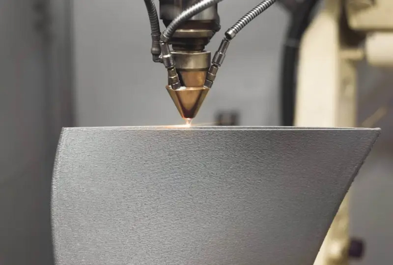
Directed energy deposition (DED) fuses materials (usually metal) by melting them as they’re being deposited.
With DED, powder or wire is pushed through a nozzle and melted by an intensely focused energy source (usually a laser) at the point of deposition. The molten material is incorporated into the energy flow, melting and depositing at the same time. The nozzle can move in multiple directions (five-axis), which gives it freedom of movement not seen in most other AM technologies. This process can deposit the molten material onto a build platform or alternatively onto a component that needs to be repaired and/or modified. DED is similar to the traditional welding process but, unlike welding, can produce fine detail.
Types of Directed Energy Deposition
The DED process can be subdivided into categories based on the energy source for making the material molten, but they’re all based on similar principles:
- Laser Engineered Net Shaping (LENS)
- Electron Beam Additive Manufacturing (EBAM)
- Wire Arc Additive Manufacturing (WAAM), which is plasma or electric-based
- Other names include Directed Light Fabrication (DLF), Direct Metal Deposition (DMD), or 3D Laser Cladding
Advantages of Directed Energy Deposition
- Can add material to existing parts because it can deposit material from many angles
- A wide selection of inexpensive print material is available, which are also used for welding
- Large build area
- Creates dense, strong parts that have great mechanical properties
- Fast build times and minimal material waste
- Can utilize multiple materials
Disadvantages of Directed Energy Deposition
- Expensive equipment, so costly initial outlay compared to most other AM processes
- Support structures are difficult because the large liquid melt pool at the point of deposition doesn’t allow for overhang
- The energy required to maintain the melting point creates thermal gradients that can cause residual stress
- Parts may require post-processing due to poor process resolution
Applications of Directed Energy Deposition
- Repair, maintenance, and feature additions of functional or structural parts, especially in heavy industry and machinery
- Useful for applications in space because the process doesn’t require gravity
- Near-net-shape part production
- Parts produced using specialist hybrid manufacturing machines
3. Material Extrusion (MEX)

Material extrusion (MEX) is a process in which material is selectively dispensed through a nozzle or orifice.
Material extrusion (MEX) is the least expensive AM method and can only use plastic polymer as the raw material. It’s usually called fused deposition modeling (FDM) because it’s a famous registered trademark. MEX/FDM varies from other AM processes because the material is added through a heated extrusion nozzle under constant pressure and in a continuous stream. With MEX/FDM, the material feeds into the printer from a coil/spool, and the machine produces parts by layering extrusions of molten thermoplastic filament. The molten plastic is continuously deposited at specific locations, where it then cools and solidifies. The fusion of the layers is achieved by precise temperature control or with chemical bonding agents.
Types of Metal Extrusion
- Fused deposition modeling (FDM) – this process name is a registered trademark
- Fused filament fabrication (FFF) is another term used but is similar to FDM
Advantages of Material Extrusion
- Affordable, entry-level pricing is available for desktop MEX printers
- The equipment is usually small, user-friendly, and affordable
- Low-temperature process
- Fast printing times for single/small parts
- Wide selection of inexpensive print material
- Easy-to-handle raw material
- Minimal post-processing required
Disadvantages of Material Extrusion
- Heating method uses low temperatures, limiting the process to plastic polymers
- No economies of scale, so high-volume runs are slow
- Low accuracy that often leaves visible layer lines
- The resolution relates to the filament, which isn’t thin enough for fine detail
- The component strength is weak in the vertical direction.
- Parts are susceptible to warping and shrinkage
- Parts are anisotropic
- Some materials can be toxic
Applications of Material Extrusion
- Prototyping, especially proof of concept and rapid prototyping.
- Buildings can be made with concrete extrusion machines
- Human tissues and organs
- Small-scale production of functional parts and prototypes
- Jigs and fixturing
4. Material Jetting (MJT)

Material jetting (MJT) is a process in which droplets of feedstock material are selectively deposited.
Material jetting (MJT) is one of the fastest, most accurate AM technologies. Although MJT is relatively new, it has a ton of potential. The MJT process begins by melting a photoreactive resin into a liquid photopolymer. A print head moves horizontally across the print bed and sprays precise micro-droplets of the liquid polymer onto the build platform either continuously or on demand. They are then cured, usually by UV light, to become solid. One printhead can house jets for multiple materials, which means multi-material printing, full-color printing, and disposable support structures in another material, such as wax, are possible.
Types of Material Jetting
The MJT category can be subdivided into several distinct printing technologies. Components produced by nanoparticle jetting (NPJ) and drop-on-demand (DOD) processes have better mechanical properties than PolyJet components. However, the basic principles for all of them are the same:
- PolyJet: In this process, the printer selectively jets a micro-thin layer of photopolymer material onto the platform, and the UV light immediately cures the layer. PolyJet is by far the most popular MJT process.
- Nanoparticle jetting (NPJ): This process is unique because it uses cartridges containing solid metal nanoparticles suspended in a liquid. Two printheads jet fine droplets of build and support materials simultaneously to form a layer. The print bed has a high temperature of around 300 C and immediately evaporates the liquid, leaving behind the solid nanoparticles. The parts are cured once all the layers are deposited.
- Drop on demand (DOD): This process is similar to PolyJet but only deposits dots as required (on demand) and not continuously. The printhead is unique because it can print curves in high resolution.
Advantages of Material Jetting
- This AM process offers the highest resolution and accuracy available
- Can print incredibly realistic objects with intricate shapes and sharp edges
- Can layer multiple materials so multicolor is possible
- Very smooth surfaces
- While not achieving the same level of tolerance as PBF, still produces parts with very high tolerances
- Large build area
Disadvantages of Material Jetting
- The equipment is expensive, and build time is slow because it constructs one droplet at a time
- Support structures must be solid, which creates significant material waste
- Materials are limited and expensive, with wax-like substances being the most common option, which may result in fragile prints
- Due to their poor mechanical properties, these parts are not typically suitable for functional use since they tend to be brittle and unable to bear significant loads
Applications of Material Jetting
- Highly realistic prototypes
- Injection mold manufacturing
- Patterns for investment castings, specifically in the jewelry industry
- Medical devices, surgical tools, and anatomical models
5. Powder Bed Fusion (PBF)
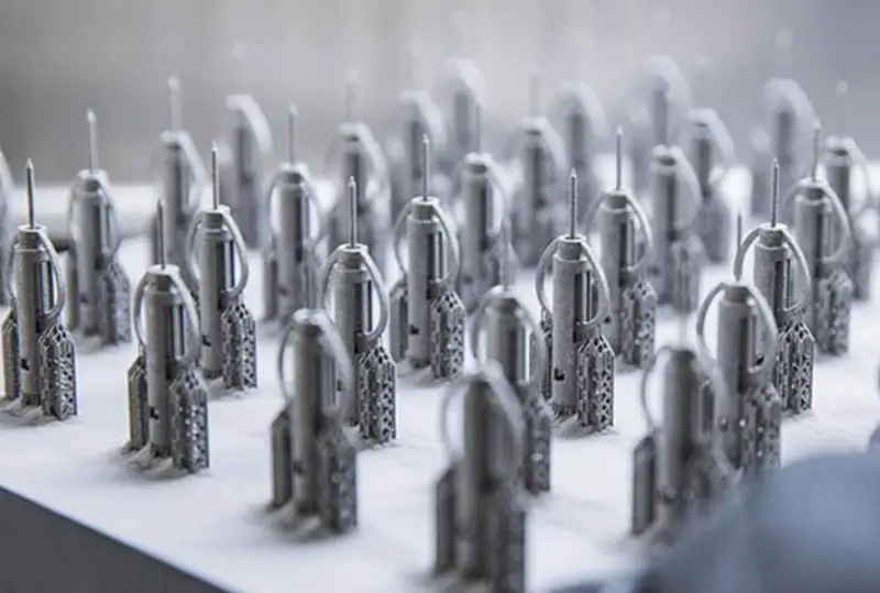
Powder bed fusion (PBF) is a process in which thermal energy selectively fuses regions of a powder bed.
Powder bed fusion (PBF) uses an energy force to selectively melt or sinter powdered material. A large bed of powdered material is heated to just below its melting point and spread over the build platform in a fine layer. The energy source (usually a laser or electron beam) is then directed across the powder’s surface, which bonds the powder, forming a thin layer of combined material. Most PBF processes happen in a near-vacuum chamber with an inert gas that protects the object from corrosion/oxidation. PBF is the most common technology for the additive manufacturing of metallic parts for aerospace and biomedical applications.
Types of Powder Bed Fusion (Proprietary)
- Selective laser sintering (SLS): Produces parts using a laser to sinter particles together selectively. It differs from the other PBF processes in the material powder used (thermoplastics like nylon and Alumide).
- MJF (by HP): Very similar to SLS.
- Selective laser melting (SLM): A similar process to SLS, but the laser doesn’t sinter; it actually melts particles together, which takes more heat.
- Direct metal laser sintering (DMLS): In broader terms, DMLS is similar to SLS. However, DMLS is optimized for 3D printing metals and alloys.
- Electron beam melting (EBM): Uses electron beams which are more powerful than a laser beam, which makes the process faster. However, parts processed by EBM have a higher surface roughness than parts produced using a laser beam.
- Selective heat sintering (SHS): Similar to SLS, however, SHS uses a thermal print head to sinter powder rather than a laser. SHS was developed by a team of doctors at the University of Texas in the 1980s and is not used often today.
- High-speed sintering (HSS): Combines the advantages of two AM technologies: SLS and binder jetting (BJT). In this process, the whole building platform is printed in one go. A layer of powder is deposited, an inkjet printhead then deposits a radiation-absorbing material (RAM) onto the desired area, and an infrared lamp then irradiates the entire surface.
Advantages of Powder Bed Fusion
- Parts have tolerances equal to VPP, but PBF parts are generally stronger
- Can produce parts with complex shapes
- Mechanical properties of metal parts are comparable to machining and casting
- Capable of functional plastic parts
- A wide range of materials is available
- Multiple materials in one build are possible
- More than one part can be produced simultaneously
- No minimum support structures are needed for the build (plastic)
- Used powder can be recycled
Disadvantages of Powder Bed Fusion
- Long print time and costly post-processing
- Expensive material and lots of electricity used, especially when the raw material is metal
- Since it requires a bed of powder, it's unsuitable for an office environment
- Parts have varied surface texture quality
- Parts can have thermal distortion – primarily with polymer parts
Applications of Powder Bed Fusion
- Low volumes of functional parts across all industries, especially medical and defense-related, and aerospace
- Common applications include one-off industrial hardware such as machine parts, jigs, grips, and fixtures, and low-volume production runs of customized plastic components
- Rapid prototyping of complex parts
- Heavily used for production parts
- Architecture models (SLS)
6. Sheet Lamination (SHL)
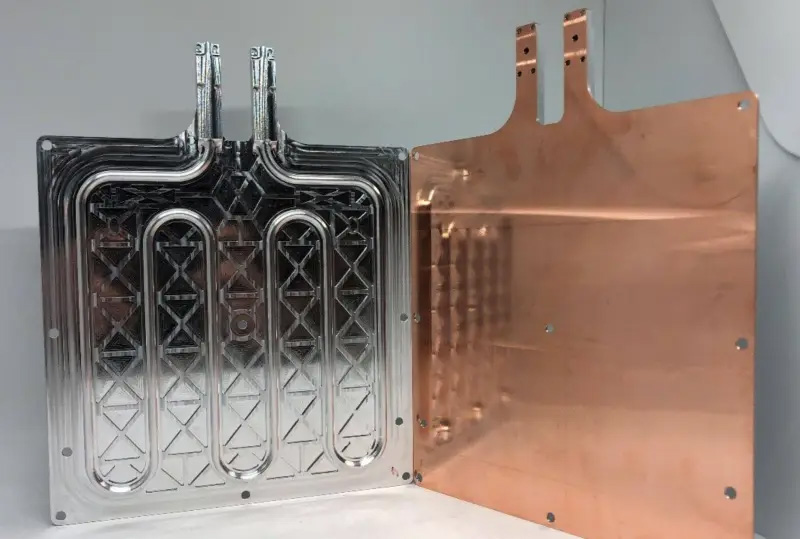
Sheet lamination (SHL) is a process in which sheets of material are bonded to form a part.
Sheet lamination (SHL) is a simple method of AM. It’s mainly used to produce colored objects in a high resolution. SHL is essentially a process of stacking very thin sheets of material and laminating them together through ultrasonic welding, bonding, or brazing. Thin layered materials like aluminum foil or paper-based filaments are bonded and cut into shaped layers by lasers or sharp blades. The most common SHL technology is ultrasonic consolidation (UC) or ultrasonic additive manufacturing (UAM). In this technique, room-temperature metal sheets are bonded together by the application of ultrasonic waves and mechanical pressure. The final object is made by laser/knife cutting/CNC machining.
Types of Sheet Lamination
Several different proprietary SHL technologies have different materials, lamination, and cutting methods. In most cases, the process is a simple variation of paper laminated object manufacturing (LOM). UC is the only technology that’s different from LOM because it uses ultrasonic welding rather than a bonding agent.
- Laminated object manufacturing (LOM): This process laminates sheets with a bonding adhesive and subtracts features layer by layer.
- Selective lamination composite object manufacturing (SLCOM)
- Plastic sheet lamination (PSL)
- Computer-aided manufacturing of laminated engineering materials (CAM-LEM)
- Selective deposition lamination (SDL)
- Composite-based additive manufacturing (CBAM)
- UC/UAM: Follows the same process at LOM, except the lamination is achieved through ultrasonic vibrations as a form of friction welding
- Composite fiber (SLCOM)
Advantages of Sheet Lamination
- Little to no pre-production; fast print time; relatively low cost
- Easy material handling
- No support structures needed
- Large build area
- Ability to layer multiple materials so multicolor is possible
- Minimal energy consumption
- Ability to integrate into a hybrid manufacturing system
- In some instances, cut material can be recycled easily
Disadvantages of Sheet Lamination
- Parts with complex shapes aren't possible
- Parts with internal voids and cavities are difficult to produce
- Adhesive bonds deteriorate over time, so the process isn’t ideal for parts that will be used long-term
- Generates a lot of material waste if the part is smaller than the sheet size or build area
- Requires time-consuming post-processing
- Limited to materials that can come in sheets
- Layer height can’t be changed without changing the sheet thickness
- The finish achieved is sometimes variable
Applications of Sheet Lamination
- Building models for architectural projects
- Colored objects for proof-of-concept and look-and-feel prototyping
- Rapid prototyping for parts without complex geometries
7. Vat Photopolymerization (VPP)
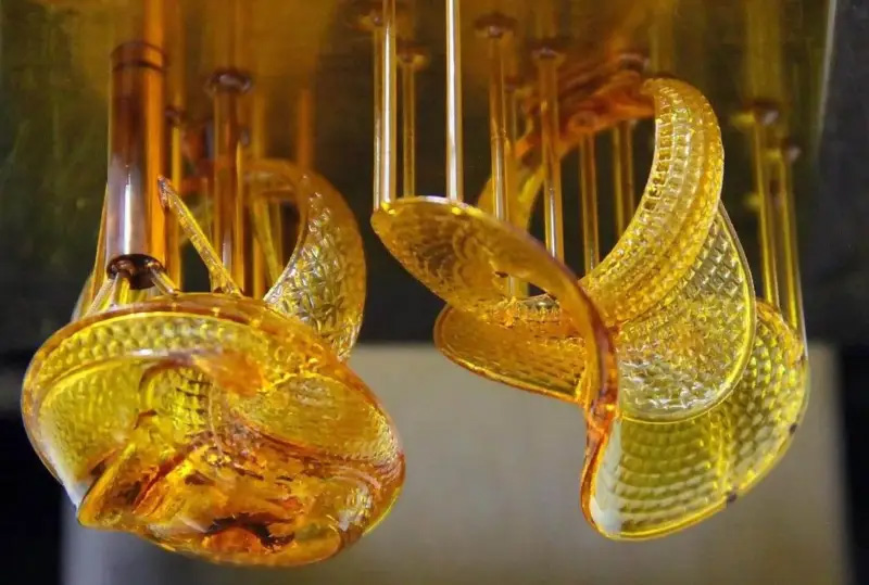
Vat photopolymerization (VPP) is a process in which liquid photopolymer in a vat is selectively cured by light-activated polymerization.
Vat photopolymerization (VPP) was the first industrial AM technology and is generally considered one of the fastest AM technologies. It can create incredibly detailed parts. Micro-stereolithography, for instance, precisely prints parts on the nanometric scale. Some resins used in VPP are biocompatible, so it’s one of the best technologies for printing medical implants. Photopolymerization is essentially a process in which photopolymer liquid resins in a vat are selectively exposed to UV light. When exposed, these materials undergo a chemical reaction and become solid. Conventionally, this light is a laser beam that draws the shape of each layer into the resin-filled vat. Once the part is complete, it is post-processed in a chamber with additional UV light. VPP is like MJT, except the material rests in a vat rather than being jetted.
Types of Vat Photopolymerization
There are three categories of VPP that differ in the light source and how light is directed. Stereolithography is the most popular.
- Stereolithography (SLA): uses a single-point laser to trace a thin line along the surface of the resin, filling in the shape of the cross-sectional layer to be cured.
- Digital light processing (DLP): Uses a digital light projector to flash a single image of an entire layer all at once.
- Continuous digital light processing (CLIP): The same as DLP, except the build platform moves in a continuous motion.
Advantages of Vat Photopolymerization
- One of the fastest AM technologies
- Parts can have incredibly small complex features with a very realistic finish
- Can be watertight and/or airtight once cured
- Parts have a smooth surface finish
- Consistent repeatability
- Large build area
- Resin drained after the build can be used again
- Biocompatible materials available
Disadvantages of Vat Photopolymerization
- Relatively expensive resin and limited materials are available
- Long post-processing time
- Can become brittle, especially when exposed to prolonged sunlight
Applications of Vat Photopolymerization
- Jewelry (short runs/prototyping)
- Dental applications
- Medical applications
- Aerospace (short runs/prototyping)
- Automotive (short runs/prototyping)
To learn more about Altair’s additive manufacturing capabilities, visit https://www.altair.com/additive-manufacturing/.
Photo Credits
- Binder jetting photo courtesy of Oak Ridge Labs
- Direct energy deposition photo courtesy of Brandenburg University of Technology (WAAM printing)
- Material extrusion photo courtesy of Canva (FDM printing)
- Material jetting photo courtesy of Solidscape (DOD printing)
- Powder bed fusion photo courtesy of Protolabs
- Sheet lamination photo courtesy of Fabrisonic (UAM printing)
- Vat photopolymerization photo courtesy of Akhani3D